EBSILON®Professional Online Documentation


|
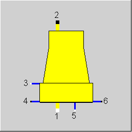
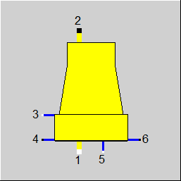
Line connections |
|
|
|
1 |
Air inlet |
|
|
2 |
Air outlet |
|
|
3 |
Cooling water inlet (warm water) |
|
|
4 |
Cooling water outlet (cold water) |
|
|
5 |
Make-Up water inlet |
|
|
6 |
Blow down |
|
General User Input Values Characteristic Lines Physics Used Displays Example
The component "wet cooling tower" simulates the operating performance of wet natural draft cooling towers under nominal and part-load conditions. In the design mode, the user defines a desired cold water temperature and the cooling range is calculated, using the nominal values of the main boundary conditions
In off-design mode, the cold water temperature is calculated as a function of the four main boundary conditions and a performance model developed by KLENKE (BWK, 18, 1966).
To estimate cooling tower performance for natural draft and mechanical draft cooling towers applying performance rules defined in DIN 1947, use components 78 and 79.
The essential quantities of heat and mass flow can best be modelled by means of an h-x diagram for wet air. The following indices are used to identify the main streams:
1 Air inlet
2 Air outlet
3 Warm water inlet
4 Cold water outlet
4id minimum possible (or ideal) cold water temperature
Other mass flows used in the model are make-up water (M5) and blow down (M6), which are determined from the mass balance equation for water.
M3-M4 = M1*(X2H2O-X1H2O) (1)
M3*H3 - M4*H4 = M1*(H2-H1) (2)
with
M3, M4 Water flow rate
M1 Dry air flow rate
X2H2O, X1H2O Water concentrations on a dry air basis.
H1, H2, H3, H4 Enthalpies
Transformation of equation (1) and (2) results in the definition of the air-to-water ratio (L)
L = M1/M3 = (H3-H4)/(H2-H1 - H4*(X2H2O-X1H2O) (3)
The KLENKE model suggests a description of the cooling tower performance with a single characteristic curve. This characteristic curve correlates the cooling tower effectiveness with the relative air-to-water ratio. The cooling tower effectiveness (α) is defined as the ratio of the actual cooling range to the “ideal” cooling range. The relative air-to-water ratio is defined as the ratio of the actual air-to-water ratio (L) over the “ideal” air-to-water ratio (Lid).
Dependent Variable (y-Axis): α = (T3-T4)/(T3-T4id) (4)
Independent Variable (x- Axis): β = L/Lid (5)
The ideal air-to-water ratio can easily be calculated from equation (3) by using “ideal” conditions for state point 4.
Normally, cooling tower performance needs to be described by a characteristic performance map containing multiple characteristic curves. KLENKE showed in his work that under the condition of a constant ratio of the total mass transfer surface area (surface of all droplets) over the water flow rate a single characteristic curve is sufficient to describe the cooling tower performance.
For simulating the operating performance, it is useful to normalize the characteristic curve around the nominal load point (design case), i.e. use it in terms of α/αN and β/βN.
To describe the design case completely, an input must be provided for the air-to-water ratio (M1/M3) in addition to the four main input parameters. A value of 0.7 is common for natural draft cooling towers.
T4id (iteration)
T2, X2 from balance equations (iteration)
(M1/M3)id
αN, βN
T4id
M1 by iteration from the cooling tower draft (stack draft)
T2, X2 (iteration)
(M1/M3)id
β from M1 and M3
β/βN and determination of α/αN from the characteristic line
T4 from α/αN and T3 - T4id
|
M1M3N |
Air-to-Water Ratio (nominal) M1N/M3N |
|
|
T4N |
Temperature of cooling water outlet (nominal) |
|
|
T1 |
Temperature of air inlet |
|
|
PHI1 |
Inlet Air Humidity PHI=Pwater / Psat(T) |
|
|
MSM3 |
Drift loss fraction MSpray/M3 |
|
|
M6M3 |
Blow down mass flow M6/M3 |
|
|
DP34N |
Pressure loss (nominal) |
|
|
CC1 |
Characteristic lines coefficient 1 |
|
|
CC2 |
Characteristic lines coefficient 2 |
|
|
CC3 |
Characteristic lines coefficient 3 |
|
|
FMODE |
Flag for calculation mode Like in Parent Profile (Sub Profile option only) Expression =0: Circulation =0: Global =1: local off-design |
|
|
FSPEC |
Make-Up Mode Like in Parent Profile (Sub Profile option only) Expression =0: Circulation mode =1: Discharge operation (zero Make-Up) |
|
|
DT34N |
Cooling range (nominal) DT34N=(T3-T4)N |
|
|
T1N |
Inlet Air Temperature (nominal) |
|
|
PHI1N |
Inlet Air humidity (nominal) |
|
|
M3N |
Cooling water mass flow (nominal) |
The parameters marked in blue are reference quantities for the off-design mode. The actual off-design values refer to these quantities in the equations used.
Generally, all inputs that are visible are required. But, often default values are provided.
For more information on colour of the input fields and their descriptions see Edit Component\Specification values
For more information on design vs. off-design and nominal values see General\Accept Nominal values
DTTID = T3-T4id
DTTNID = T3N-T4Nid
DTTNR = DTTN/DTTNID
M1M3NR = M1M3N/M1M3NID
DTTVV = M1M3/M1M3ID/M1M3NR
Characteristic line (DTTVV):
ZW =(DTTV+CC1*(DTTVV^0.3-DTTVV)+CC2*(DTTVV^1.3-DTTVV^2) )* (1+CC3*(T1-T1N)*0.01)
DTT = ZW*DTTID*DTTNR
T4 = T3-DTT
|
All cases |
||
|
M1M3=M1/M3 DTTN=DT34N Pre-calculation if GLOBAL = off-design or iteration > 15, then {calculation of off-design} H1N = H1 if GLOBAL = Design, then { T3N = f (P3, H3) DTTN= T3N-T4N H3N = H3} else { T3N = T4N+DTTN H3N = f (P3, T3N) }
CALL Humidity (PHI1N,T1N,P1,X1i) T4Nid = T_LIMIT (PHI1N,T1N,P1,X1i) H4N = f (P4,T4N) INDI = 0 H2N = H2_M1M3(PHI1N, T1N, P1N, H1N, X1i, T3N, P3, H3N, T4N, P4, H4N, M1M3NID= M1M3_ID (T1N, T3N, H1N, H3N, T4Nid, X1i, X2i) Reference values of characteristic lines { DTTNID = T3N-T4Nid DTTNR = DTTN/DTTNID M1M3NR = M1M3N/M1M3NID } Assignments { H1X = H1N H2X = H2N H4X = H4N H6X = H4N DTT = DTTN M1M3 = M1M3N } Calculation of partial load ========================== T3 = f (P3,H3) CALL Humidity (PHI1,T1,P1,X1i) T4id = T_LIMIT (PHI1,T1,P1,X1I) DTTID = T3-T4id M1M3ID = M1M3_ID (T1, T3, H1, H3, T4id, X1I, GEW2) INDI = 2 H2N = H2_M1M3(PHI1N, T1, P1, H1, X1I, T3, P3, H3, T4, P4, H4, Assignments { H1X = H1 H2X = H2 H4X = H4 H6X = H4 DTT = T3-T4 } Equations for pressure ======================== F = 1.0 F = (M3/M3N) ** 2 at MODE = 1 DP34 = DP34N * F P4 = P3 - DP34 P2 = P1 P4 = P6 P4 = P5
Equations for enthalpy ======================= H1 = HX1 H2 = HX2 H4 = HX4 H6 = HX6
Equations for mass flow =========================
ZWG = (X2H2O-X1H2O)*M1M3
if FSPEC = 0, then { M3 = M4 } , else { M3*(M6M3+ZWG+MSM3) = M4 } M1 = M1M3*M3 M2 = (1+(ZWG+MSM3)/M1M3)*M1 M6 = M6M3*M3 if FSPEC=0, then { M5 = (M6M3+ZWG+MSM3)*M3 } else { M5 = 0 } °°°°°°°°°°°°°°°°°°°°°°°°°°°°°°°°°°°°°°°°°°°°°°°°°°°°°°°°°°°°°°°°°°°° Subroutine Humidity Determine water mass concentration at given pressure, °°°°°°°°°°°°°°°°°°°°°°°°°°°°°°°°°°°°°°°°°°°°°°°°°°°°°°°°°°°°°°°°°°° Humidity (PHI,T,P,X) ===================== PS = Psat(t) PH2O= PS * PHI YH2O= PH2O/P XH2O= YH2O*MolH2O/MolSUM °°°°°°°°°°°°°°°°°°°°°°°°°°°°°°°°°°°°°°°°°°°°°°°°°°°°°°°°°°°°°°°°°°°° Subroutine T_LIMIT Calculation of the wet bulb temperature at given system °°°°°°°°°°°°°°°°°°°°°°°°°°°°°°°°°°°°°°°°°°°°°°°°°°°°°°°°°°°°°°°°°°°° T_LIMIT (PHI,T,P,Xi) =================== H = f (P,T,Xi) TLIM = T XLIM_H2O_G= f (P,TLIM) (maximum steam portion) XLIM_H2O = XLIM_H2O_G
Iteration{DH2O = (MLIM_H2O-M1H2O)/M1 DH2O = (XLIM_H2O-X1H2O)/(1.0-XLIM_H2O) HLIM= H1+DH2O*(CPWater*TLIM-LH2O) LH2O=latent heat in water TLIM= f (HLIM,P) XLIM_H2O_L=f (P,TLIM) (maximum water portion) if XLIM_H2O_L >0 then { XLIM_H2O_G = XLIM_H2O_G-XLIM_H2O_L } else { XLIM_H2O_G = f (P,TLIM) (maximum steam portion) }
XLIM_H2O = XLIM_H2O_G } End of the iteration T_LIMIT = TLIM °°°°°°°°°°°°°°°°°°°°°°°°°°°°°°°°°°°°°°°°°°°°°°°°°°°°°°°°°°°°°°°°°°°° Subroutine H2_M1M3 Calculation of the enthalpy of the cooling tower outlet at °°°°°°°°°°°°°°°°°°°°°°°°°°°°°°°°°°°°°°°°°°°°°°°°°°°°°°°°°°°°°°°°°°° H2_M1M3 (PHI1,T1,P1,H1,X1i,T3,P3,H3,T4,P4,H4,
T2 = T3 START of the iteration { CALL humidity (PHI=1,T2,P2=P1,X1i) if INDI=0, then { M1M3 = M1M3N (= Ratio M1/M3) } else { M1M3 from M1M3N, DENSITY12 , DENSITY12N and fireplace formula Characteristic line DTTVV = M1M3/M1M3ID/M1M3NR ZW = Characteristic line (DTTVV) ZW =(DTTV+CC1*(DTTVV^0.3-DTTVV) +CC2*(DTTVV^1.3-DTTVV^2) )* (1+CC3*(T1-T1N)*0.01) DTT = ZW*DTTID*DTTNR T4 = T3-DTT H4 = f (P4,T4) } Energy balance of the cooling tower ZW2 = (X2H2O-X1H2O)/(1-X2H2O) H2 = (H1+(H3-H4)/M1M3+(H4-LH2O)*ZW2)/(1-ZW2) T2 = f (H2,P2) } End of the iteration H2_M1M3 = H2 °°°°°°°°°°°°°°°°°°°°°°°°°°°°°°°°°°°°°°°°°°°°°°°°°°°°°°°°°°°°°°°°°°°° Subroutine M1M3_ID Calculation of the minimal air-to-water ratio M1/M3id for °°°°°°°°°°°°°°°°°°°°°°°°°°°°°°°°°°°°°°°°°°°°°°°°°°°°°°°°°°°°°°°°°°°° M1M3_ID (T1id,T3id,H1,H3,T4_LIMIT,X1i,X2i) T4id = T4_LIMIT T2id = T3id H1id = H1 H3id = H3 H2id = f (P2,T2id) H4id = f (P2,T2id) Energy balance of the cooling tower ZW = (X2_H2O-X1_H2O)/(1-X2_H2O) M1M3_id = (H3id-H4id)/(H2id-H1id-(H4id-LH2O-H2id)*ZW) |
||
 |
Display Option 1 |
Click here >> Component 47 Demo << to load an example.