EBSILON®Professional Online Documentation


|
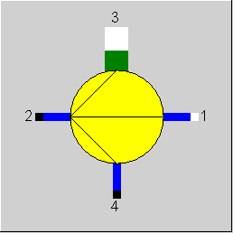
Line connections |
|
|
|
1 |
Feed water inlet |
|
|
2 |
Feed water outlet (1) |
|
|
3 |
Necessary shaft power |
|
|
4 |
Feed water outlet (2) (Injection water outlet) |
|
General User Input Values Characteristic Lines Physics Used Displays Example
Component 44 models a feed water pump with the extraction of spray water.
This Component can also be used for salt water, universal fluids, user-defined fluids, 2-phase liquid fluids, oil streams and thermal oil streams.
For pumps, the final pressure must be specified. This is usually done based on the condition of the system but can also be handled by component 33 (start value).
The pump with extraction can also be calculated in the identification mode. It is a selection between a specification of the outlet enthalpy or the pump performance is possible.
Losses
Both constant and output-dependent mechanical losses can be considered. The specification value QLOSSM is used for the constant losses. The output-dependent losses result from the mechanical efficiency ETAMN.
The sequence in which the proportional and the constant fraction are considered depends on the direction of the energy flow.
If both a mechanical efficiency ETAMN and a constant loss QLOSSM are specified, the two are combined as follows:
Q_gross = ( Q_net + QLOSSM) / ETAMN
The result value QLOSS comprises the entire (load-independent and load-dependent) loss
QLOSS = Q_gross – Q_net
The result value ETAM contains both fractions (as in the case of Component 6), as ETAM is defined by
ETAM = Q_net / Q_gross
If a QLOSSM > 0 is specified, ETAM thus no longer equals ETAMN but is accordingly smaller (by QLOSSM/heat input).
For the component 44, the efficiency line CETA is set to ETAI / ETAIN = 1, the calculation mode of this pump corresponds to the calculation mode of the pump 8 in mode (FCALC = 0).
In all load cases, either mass flow and outlet pressure can be specified. The calculation of the mass flow from the pressure is not possible.
Of course, the possibility to specify mass flow and pressure at the same time independently of each other (FSPECP=-1) facilitates the modeling; however, in reality it can only be achieved by the fact that either the pump can be operated with variable rotational speed or it has a control valve downstream of the pump. The variant with the control valve, however, is unfavorable because thereby a part of the pump output has to be used for an unnecessary pressure increase that subsequently is throttled again. The advantage of the rotational speed control is that the efficiency of the pump changes only little across the entire load range as the rotational speed is always adjusted accordingly. Therefore the efficiency characteristic line CETA that is used in simple mode has been set to 1 by default.
If pressure and flow rate are set independently of each other in the off-design range and the efficiency is decreased at a lower flow rate M1/M1N<1, unrealistic values will result for the pump output. Only if a pump is operated at fixed rotational speed will the efficiency change with the flow rate; however, at a lower flow rate the pump with fixed speed will also develop a higher pressure in proportion to the head curve.
Thus an efficiency curve can only be applied together with a pressure – flow rate curve to correctly calculate the pump output in off-design. For the throttle control it is also important to set a control valve at the outlet.
Component 8 (pump):
For the pump (without extraction of spray water), there is a new calculation mode for using relative delivery head characteristics. The handling follows the usually specified characteristic lines and facilitates easy adaptation.
Beginning with the current operating point (M, P), the two limiting points ZHF (zero head flow = flow rate the pump can provide without back pressure) and SOH (shut-off head = flow rate the pump can achieve against a closed valve) are calculated by means of the characteristic lines in the design case.
In off-design, either the mass flow or the achieved pressure can be specified, the other quantity is calculated each time. Here a minimum mass flow is adhered to.
This enhancement only applies for a fixed speed of rotation without variation of the blade position.
Component 24 (compressor):
This component is suitable for gaseous media as well as for superheated or wet steam.
|
ETAIN |
isentropic efficiency (nominal) |
|
ETAMN |
mechanical efficiency (nominal) |
|
QLOSSM |
mechanical loss (constant fraction) |
|
FMODE |
Flag for calculation mode Like in Parent Profile (Sub Profile option only) Expression =0: Global =1: Local off-design =-1: Local design |
|
FCHR |
Flag for Usage of characteristic Like in Parent Profile (Sub Profile option only) Expression =0: use ETAI from characteristic =-1: Identify ETAI by power specification =-2: Identify ETAI by H2 specification |
|
M1N |
Mass flow (nominal) |
The parameters marked in blue are reference quantities for the off-design mode. The actual off design values refer to these quantities in the equations used.
Generally, all inputs that are visible are required. But, often default values are provided.
For more information on colour of the input fields and their descriptions see Edit Component\Specification values
For more information on design vs. off-design and nominal values see General\Accept Nominal values
|
Characteristic line 1: CETA isentropic efficiency characteristic line ETAI/ETAIN = f (M1/M1N) CETA set to 1 by default! |
|
X-axis 1 M1/M1N 1st point |
The calculation model of the pump is based on the assumption that a change in the conditions can be described with the isentropic efficiency.
The following equations are used for the mass balance, pressure and enthalpy:
Mass flow: M1 = M2 + M4
two of these three mass flows are defined by another component.
Pressure:
All pressures are defined by other components under the boundary condition that P4 <= P2.
Enthalpy:
Step 1: Calculation of the isentropic state change from the inlet condition P1, S1 to the state P2, S2 with S2=S1.
The enthalpy difference of the isentropic state change is calculated with
H2S = H(P2,S2)
DHS = H2S - H1
Step 2: The real change of the enthalpy results from the DHS and the isentropic efficiency ETAI to
DH = DHS/ETAI
The outlet state results from P2 and
H2 = H1 + DH
The state change for the intermediate state 4 (water extraction) is calculated accordingly from 1 to 2. However, P4 is used instead of P2 for the outlet pressure.
The isentropic efficiency results from the specification value in the design case. For off-design, this value is modified by a characteristic line function for the mass flow ratio.
|
All cases |
||
|
from characteristic line: ETAI = ETAIN * f (M1/M1N) S1 = f(P1,H1) T2S = f(P2,S1) H2S = f(P2,S1) DH2S = H2S - H1 DH2 = DH2S/ETAI H2 = H1 + DH2 T4S = f(P4,S1) H4S = f(P4,S1) DH4S = H4S - H1 DH4 = DH4S/ETAI H4 = H1 + DH4 T2 = f(P2,H2) T4 = f(P4,H4) M2 = M1 - M4 M3*H3 = (M2*H2 + M4*H4 - M1*H1)* ETAMN |
||
 |
Display Option 1 |
Click here >> Component 44 Demo << to load an example.