EBSILON®Professional Online Documentation


|
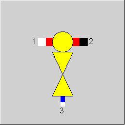
Line connections |
|
|
|
1 |
Fluid inlet |
|
|
2 |
Fluid outlet |
|
|
3 |
Injection line |
|
General User Input Values Physics Used Displays Example
Component 38 is used to model an injection of water or steam into other fluids, that may have water or steam as part of their composition. With component 38, a transition from the water/steam table to the corresponding fluid table is performed (with consideration of different zero levels of the enthalpy).
Component 38 can also be used to model an injection of steam into water (as an alternative to component 3, mixer with throttle). It is also possible to specify the mixing temperature from outside instead of the injection quantity. However, this mode is numerically very sensitive. In case of convergence problems, regulate the injection quantity through a controller.
FSPECX allows defining on which pins a composition is to be specified. However, this flag can only be used if the material equations are integrated into the equation system.
(Model option -->Simulation --> Iteration, Level of integration of material equations).
Table Differences for Injections
In the case of the component “Water injection“ (38) as well as both saturizer components (53, 97) it is necessary to transfer the injected water that is calculated in the injection line according to the water/steam table (usually IAPWS-IF97) into the flue gas/ air etc., where the calculation is carried out with pressure-independent FDBR polynomials. There are different options regarding the point where this table transfer is carried out; these lead to slightly different results in each case. These differences are due to the fact that the treatment of the steam as ideal gas represents an approximation that becomes inaccurate at high pressures and lower temperatures in particular. In concrete terms this means that the modeling of the injection will become the more realistic the later the table transfer takes place.
It is possible to do this table transfer one step later.
This can be set using the flag FTABC (detailed description see Release -Notes 12. Chapter 1.3.5.)
Here the previous results can be reproduced with FTABC=0,
with FTABC=1 It is possible to do this table transfer one step later.
Kernel expression EDHTAB
This component allows to mix substances with different physical properties tables, in particular with different reference values for the enthalpy. Here the calculation of the table difference (i.e. the enthalpy difference for the same state point between the two tables) is crucial for the functionality of the component. There were two calculation variants to choose from before. There were two calculation variants to choose from before.
An own algorithm for determining the table difference can be specified in the Kernel expression EDHTAB.
To do so, the flag FTABC has to be set to 2 (“Table difference calculated by Kernel expression EDHTAB“).
FTABC=2 : Table difference calculated by Kernel expression EDHTAB
Internal Specification of the Mixing Temperature
The injection now allows to enter the desired mixing temperature as specification value TMIX. To do so, the flag FSPEC has to be set to the value 1.
If the inlet temperature is higher than TMIX, the injection mass flow will be calculated in such a way that the desired mixing temperature is achieved.
In the case of lower inlet temperatures, the injection mass flow is set to 0 and the outlet temperature equals the inlet temperature.
In contrast to FSPEC = -1 (“Mixing temperature given externally“), FSPEC = 1 is the more robust variant as when specifying externally, the set temperature will be adhered to in each case, which leads to an error situation when the inlet temperatures are too low. As this situation can also occur temporarily in the course of the iteration, it is recommended not to use FSPEC = -1.
Injection of 2-phase fluids
In Component 38 it is possible to inject not only water but other liquids as well. Until Release 11 this was limited to ammonia and CO2. In Release 12, however, all 2-phase fluids are admitted that can also occur in the flue gas line, even if they as treated as a gas in the flue gas line as a rule, i.e. n-butane, isobutane, methanol, ethanol, hydrogen, helium, nitrogen, propane, cyclopentane, isopentane, neopentane, hexane, toluene, nonane, decane, carbon monoxide, carbonyl sulfide, hydrogen sulfide, sulfur dioxide, 1-butene, argon, dodecane, C2-butene, ethane, ethene, heptane, isobutene, isohexane, krypton, methane, neon, octane, pentane, propene, T2-butene, xenon, methylcyclohexane, phenylethane, hydrogen chloride, and ortho-xylene (1,2-dimethylbenzene). If so large an amount is injected that a fraction remains in the liquid phase, the calculation will become accordingly inaccurate. However, this component offers possibilities to detect this situation and to estimate the inaccuracy:
The result values XIL2 and XIV2 specify which fraction of the injected fluid is in the liquid and which one is in the gaseous phase.
The result values XL2 and X2 specify which fraction of the entire fluid streaming out are liquid and gaseous respectively. These values, however, are only approximations as they are only calculated on the basis of the partial pressures of the injected substance, and no complete phase equilibrium calculation is carried out, in which the interaction with other substances would have to be considered as well.
The result value DH2UNC enables an estimation of the inaccuracy of the outlet enthalpy by treating the liquid phase as ideal gas. It specifies by which amount the enthalpy of the outlet fluid would decrease if, at the same temperature, the evaporation enthalpy of the liquid fraction were subtracted. In reality, however, this situation would also lead to another temperature, so that this can only be a rough estimate of the magnitude.
The new result values, however, are only calculated at FTABC=1.
From Release 15 Patch 4, the mixing calculation is also carried out for very small mass flows. Previously, this was not done for total mass flows below 10^-6 kg/s.
|
FSPEC |
Calculation mode Like in Parent Profile (Sub Profile option only) Expression = 0: Injection mass flow given (default) = -1: Mixing temperature given externally =1: Mixing temperature given by specification value TMIX |
|
TMIX |
Mixing temperature |
|
FTABC |
Material table conversion point Like in Parent Profile (Sub Profile option only) Expression = 0: For all the water at outlet temperature and total pressure (old mode) = 1: For gaseous fraction of water after expansion to partial pressure = 2: Table difference calculated by Kernel expression EDHTAB |
|
EDHTAB |
Function for table difference function evalexpr:REAL; begin evalexpr:=2500.0; end; |
|
FSPECX |
Flag for Handling - Material-equation Like in Parent Profile (Sub Profile option only) Expression =0: Any given |
Generally, all inputs that are visible are required. But, often default values are provided.
For more information on colour of the input fields and their descriptions see Edit Component\Specification values
For more information on design vs. off-design and nominal values see General\Accept Nominal values
|
All cases |
||
|
M2 = M1 + M3 P2 = P1 Hdiff = 0 if line 1, 2 = flue gas or air and line 3 = water, then { Hdiff = -2500 kJ/kg } H2*M2 = H1*M1 + (H3+Hdiff)*M3 t2 = f(p2,h2) if wet steam at line 2, then X2 = f(P2,H2) Q2 = Q1 + Q3 NCV2 = (NCV1 * M1 + NCV3 * M3) / M2 |
||
 |
Display Option 1 |
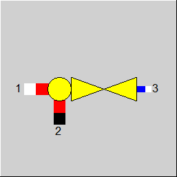 |
Display Option 2 |
Click here >> Component 38 Demo << to load an example.