

|
Line connections |
|
|
|
1 |
Electrical power |
|
|
2 |
Shaft power |
|
|
3 |
Control inlet for efficiency (as H) |
|
General User Input Values Characteristic Lines Physics Used Displays Example
The default values and characteristic lines have been updated in Release 10.
Implementing a load-independent mechanical loss (QLOSSM) (see Release-Notes for Release 12)
The sequence in which the proportional and the constant fraction are considered depends on the direction of the flow of energy.
If both a mechanical efficiency ETAMN and a constant loss QLOSSM are specified, the two are combined as follows:
Q_gross =( Q_net + QLOSSM) / ETAMN
The result value QLOSS comprises the entire (load-independent and load-dependent) loss
QLOSS = Q_gross – Q_net
The result value ETAM contains both fractions (as in the case of component 6), as ETAM is defined by
ETAM = Q_net / Q_gross
If a QLOSSM > 0 is specified, ETAM thus no longer equals ETAMN but is accordingly smaller (by QLOSSM/heat supply).
Efficiency specification via logic line
In the motor, the nominal value of the electrical efficiency can also be specified as enthalpy on the logic inlet (Pin 3) instead of in the specification value ETAEN, so that
this value can also be controlled. The flag FETAEN serves to define which specification is to be used.
Result value ETATOT
Besides the electrical and the mechanical efficiency, the total efficiency is output as result value ETATOT as well.
Default values
The previous default value for the electrical efficiency ETAEN = 0.85 is too low for big motors. The value has therefore been increased to 0.95. In the case of rated powers below 20 kW, however, a warning is output to suggest that the value should be adjusted.
Calculation of the rotational speed
The relationship between the rotational speed F2 on the mechanical shaft and the mains frequency F1 of the electric wire is considered. In the case of synchronous motors, the ratio is fixed by the (integer) number of pole pairs PP:
F2 = F1 / PP
In the case of asynchronous motors, the rotational speed is decreased by a load-dependent slippage SLIP:
F2 = (1-SLIP) * F1 / PP
The load dependence can be represented in Ebsilon via a Kernel expression. However, you can also specify the value directly. This is controlled via the flag FSLIP:
FSLIP = 0: use SLIP = 1 (synchronous motor)
FSLIP = 1: use specification value SLIP
FSLIP = 2: use value from Kernel expression ESLIP
FSLIP =-1: Shaft speed given externally, SLIP calculated (identification mode)
Since Ebsilon has not yet calculated the shaft speed on the motor, use FSLIP = -1 for compatibility with loading a circuit created with an older version of Ebsilon.
For newer models, the default setting is FSLIP=0.
Display Formats :
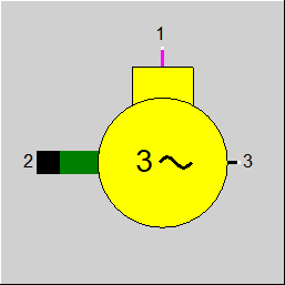
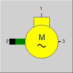
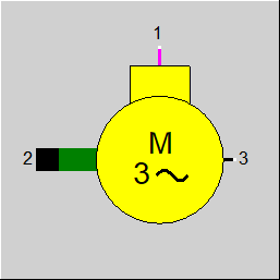
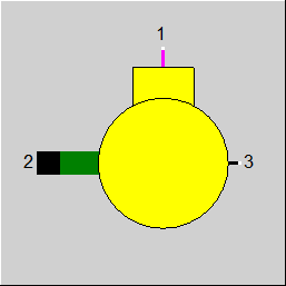
Generator: Graphical symbols can be displayed instead of or in addition to the letter “M”. (see Component Displays).
|
FMODE |
Flag for calculation mode Expression = 0: GLOBAL |
|
FETAEN |
Specification of electric efficiency Like in Parent Profile (Sub Profile option only) Expression = 0: By specification value ETAEN |
|
ETAEN |
Electrical efficiency (nominal) |
|
ETAMN |
Mechanical efficiency (nominal) |
|
QLOSSM |
Mechanical loss (constant fraction) |
|
PP |
Number of pole pairs |
|
FSLIP |
Method for slip definition Like in Parent Profile (Sub Profile option only) Expression = 0: No Slip (synchronous motor) |
|
SLIP |
Slip |
|
ESLIP |
Slip function function evalexpr:REAL; |
|
Q1N |
Nominal power |
The parameters marked in blue are reference quantities for the off-design mode. The actual off-design values refer to these quantities in the equations used.
Generally, all inputs that are visible are required. But, often default values are provided.
For more information on colour of the input fields and their descriptions see Edit Component\Specification values
For more information on design vs. off-design and nominal values see General\Accept Nominal values
|
Characteristic line 1: Electrical efficiency ETAE/ETAEN = f (Q1/Q1N) |
|
X-axis 1 Q1/Q1N 1st point |
|
KCharacteristic line 2: Mechanical efficiency ETAM/ETAMN = f (Q1/Q1N) |
|
X-axis 1 Q1/Q1N 1st point |
|
All cases |
||
|
|
Q1R = Q1/Q1N
ETAE= f(Q1/Q1N) * ETAEN corresponding to characteristic line 1
ETAM= f(Q1/Q1N) * ETAMN corresponding to characteristic line 2
H1*M1 * ETAE * ETAM = H2*M2
|
|
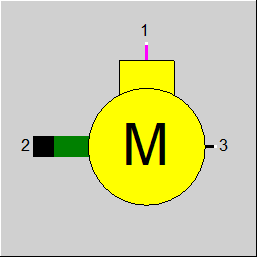 |
Display Option 1 |
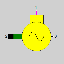 |
Display Option 2 |
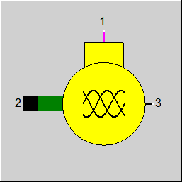 |
Display Option 3 |
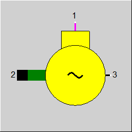 |
Display Option 4 |
 |
Display Option 5 |
 |
Display Option 6 |
 |
Display Option 7 |
 |
Display Option 8 |
Click here >> Component 29 Demo << to load an example.