EBSILON®Professional Online Documentation


|
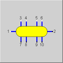
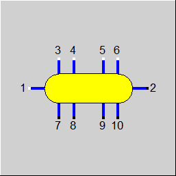
Line connections |
|
|
|
1 |
Main inlet |
|
|
2 |
Main outlet |
|
|
3 |
Sub-stream 1 inlet |
|
|
4 |
Sub-stream 2 inlet |
|
|
5 |
Sub-stream 3 inlet |
|
|
6 |
Sub-stream 4 inlet |
|
|
7 |
Sub-stream 1 outlet |
|
|
8 |
Sub-stream 2 outlet |
|
|
9 |
Sub-stream 3 outlet |
|
|
10 |
Sub-stream 4 outlet |
|
General User Input Values Physics Used Displays Example
It is assumed that all mass flows are throttled when they enter the tank. In the tank all the incoming streams mix. The mass flows coming out of the tank must be defined by component 33 (starting value). A heat loss owing to radiation can also be taken into account.
In component 28 it is possible to mix different fluids (e.g. coal and air for displaying a mill). At the outlet side, a fluid must be available, which can accept all the incoming materials. However, it is not possible to mix water and other fluids by using this component. To do this, the components 38 (water injection) and 53 (Saturizer) are suitable.
For additional material parameters (flags) like coal type, a mixing is not reasonable. In this case, the value is determined by the main input line (pin 1).
Note: Mixing of fluids:
The treatment of lines of the types “air“, “flue gas“, “gas“, “crude gas“, “coal”, “oil“, and “user-defined“ has been standardized, so that nearly the same substances can be present in each line. The substances added due to this, however, are displayed further below in the combo box, so that the handling during the input does not change.
This standardization allows mixing different fuels (e.g. oil and gas). Both Component 60 (General mixer) and Component 28 (Tank (mixing point)) can be used for this. The advantage is that due to this it is no longer necessary to model a separate combustion chamber for different fuel types in each case.
Specify the pressure PN in the container (FSPECP)
It is possible to specify a pressure PN in the tank.
The following can be set via a flag FSPECP:
|
FMODE |
Flag for calculation mode Design/Off-design Like in Parent Profile (Sub Profile option only) Expression =0: global =1: local off-design (i.e. always off-design mode, even if global design mode was selected) |
|
FSPECP |
Flag for pressure handling Like in Parent Profile (Sub Profile option only) Expression =0: Inlet pressures given externally, outlet pressures calculated from main inlet P1 and DP12N =1: All pressures given externally, PN used for plausibility checks |
|
PN |
Pressure in the tank (nominal) |
|
DP12N |
Pressure drop (nominal) |
|
DQL |
Heat loss |
|
M1N |
Mass flow at the main outlet |
The parameters marked in blue are reference quantities for the off-design mode. The actual off-design values refer to these quantities in the equations used.
Generally, all inputs that are visible are required. But, often default values are provided.
For more information on colour of the input fields and their descriptions see Edit Component\Specification values
For more information on design vs. off-design and nominal values see General\Accept Nominal values
|
All cases |
||
|
M1R = (M1/M1N) if GLOBAL = design case, then {M1R = 1} DP12 = DP12N * M1R ** 2 P2 = P1 – DP12 H2 = (M1*H1+M3*H3+M4*H4+M5*H5+M6*H6 -M7*H7-M8*H8-M9*H9-M10*H10-DQL)/M2
T2 = f(P2, H2) M2 = M1 + M3 + M4 + M5 + M6 - (M7 + M8 + M9 + M10) Q2 = M2 * H2 P7=P2 T7=T2 H7=H2 M7 taken from the default settings of the lines usedQ7=M7*H7 P8=P2 T8=T2 H8=H2 M8 taken from the default settings of the lines used Q8=M8*H8 P9=P2 T9=T2 H9=H2 M9 taken from the default settings of the lines used Q9=M9*H9 P10=P2 T10=T2 H10=H2 M10 taken from the default settings of the lines used Q10=M10*H10 |
||
 |
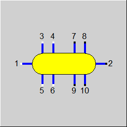
Display Option 1 |
 |
Display Option 2 |
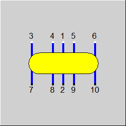 |
Display Option 3 |
Click here >> Component 28 Demo << to load an example.