
EBSILON®Professional Online Documentation


|
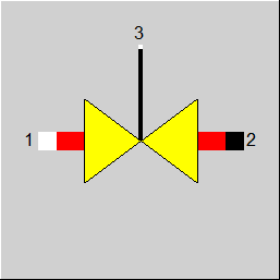
Line connections |
 |
|
|
1 |
Medium inlet |
|
|
2 |
Medium outlet |
|
|
3 |
Control inlet for pressure drop (as P) |
|
General User Input Values Physics Used Displays Example
Component 2 is used to model a defined pressure drop in a stream.
In case a heat loss is also to be modelled simultaneously, the component 13 (pipeline) can be used.
In the design case, the pressure loss DP12RN is to be specified, selectively as
Like for the piping (component 13), a flag FDP exists also for the throttle. As this component does not support a geometrical calculation, you may switch only between
These options are available for FDP12RN. Please mind, that the value of FVOL is also taken into account to calculate the pressure drop.
The formulas below are valid for FVOL=1.
For FVOL=0 the term V1/V1N is neglected (set to 1.0 resp.).
For FVOL=2 the both terms (M1/M1N)^2 and V1/V1N are neglected (both set to 1.0 resp.).
You can choose between
Design : DP12 = P1 * DP12RN
Off-Design: DP12 = P1 * DP12RN
The default setting is FDP12RN=1, which also is the most reasonable variant from a physical point of view.
These settings are used with many other components in the same way.
Convergence tuning (DPDPNMAX):
To improve convergence, the pressure drop at components 2 (throttle) and 13 (pipe) can be limited to double to ten times the nominal value - even during iteration. The partial load factor DPDPN (see below) is used for this purpose.
If this limitation remains until the end of the iteration, the component has obviously been designed at the wrong load point. In this case a warning is given. To improve convergence, the pressure drop of component 13 (pipe) can be limited by DPDPNMAX to double to ten times the nominal value.
If the calculated pressure drop exceeds DPDPNMAX times the nominal value, it is limited to this value and a warning is issued. To avoid this, a different design point should be chosen for the component.
Flag FERRP :
It was possible to specify a negative pressure drop in this component or - in the mode "P2 given from outside" - to specify the outlet pressure higher than the inlet pressure without an error message being generated.
This way, these components could also be used in special logical constructions.
As, however, this is physically impossible in the normal use of the components, a flag FERRP has been implemented that allows to define whether in this case an error message, a warning, a comment or nothing at all is to be output. The default setting for FERRP is “Warning“, so that old models continue to calculate without error message.
The user can then decide on a case-by-case basis whether to remove this warning or whether there really is an error.
As with other components FMODE=-1 is used for ”Local design“ .
Logic inlet (Connection point 3) for controlling component properties
(see also : Editing components --> Ports)
To make component properties like efficiencies or heat transfer coefficients (variation quantity) accessible from the outside (for control or reconciliation) it is possible to place the respective value on an auxiliary line as an indexed measured value (specification value FIND). In the component, the same index must then be entered as specification value IPS.
It is also possible to place this value on a logic line that is directly connected to the component (please see FVALDP=2, Variation variable: DP12RN, Dimension: Pressure).
The advantage is that the allocation is graphically visible, and errors (e.g. when copying) are thus avoided.
The activation of this logic line can also be made conditional on the mode of calculation. This way, this feature can also be used for designs without having to switch manually all the time.
For this, the flag FVALDP features the settings
This option is available for Components 2, 6, 8, 13, 18, 19, 23, 24, and 94.
The pressure losses are recorded as a result values:
Result value: Off-design factor for pressure drop (DPDPN)
Reference variables for nominal value:
|
FMODE |
Flag for calculation mode Design/Off-design Expression =0: like global in model =1: Local off-design, i.e. always off-design calculation mode, even in case of global design = -1: local design |
|
FDP |
Flag for the type of specification of design pressure loss Like in Parent Profile (Sub profile option only) Expression = 0: Use specification value DP12RN =-1: no calculation of the pressure drop, P2 given from outside |
|
FDP12RN |
Flag for pressure drop handling Like in Parent Profile (Sub profile option only) Expression =1: absolute pressure loss =2: relative pressure loss =3: relative pressure loss, relative related to design =4: relative pressure loss (simple) |
|
FVALDP |
Validation of the pressure drop Like in Parent Profile (Sub profile option only) Expression =0: DP12RN used without validation =1: (Deprecated) Pseudo measuring point identified by IPS used (can be validated) =2: DP12RN given by pressure on control inlet 3 (pressure) =4: Pressure on control inlet 3 used in design, specification value DP12RN in off-design =5: Specification value DP12RN used in design, Pressure on control inlet 3 in off-design |
|
DP12RN |
Pressure drop (nominal) [absolute or relative to P1] |
|
IPS |
Index for pseudo measuring point |
|
FVOL |
Flag for considering the specific volume on pressure drop calculation Like in Parent Profile (Sub profile option only) Expression =0: without volume effect: DP12 = DP12RN * (M1/M1N)**2 =1: with volume effect: DP12 = DP12RN * (M1/M1N)**2 * V1/V1N =2: constant value (load independent, factor=1) : DP12 = DP12RN |
|
DPDPNMAX |
Restrict off-design factor for pressure loss to (input) Value> = 1: see above under "General"; (A value <1 will give a warning! A value <1 would mean that you can not reproduce the design data in off-design mode.) |
|
FADAPT |
Flag for using the adaption polynomial or the adaption function Like in Parent Profile (Sub profile option only) Expression =0: Not used =1: Correction for pressure loss [DP = DP12 * load-dependent factor *polynomial] =2: Calculation of pressure loss [DP = DP12 * polynomial] =1000: not used, but ADAPT evaluated as RADAPT (Reduction of the computing time) = -1: Correction for pressure loss [DP = DP12 * load-dependent factor * function] = -2: Calculation of pressure loss [DP = DP12 * function] = -1000: not used, but EADAPT evaluated as RADAPT (Reduction of the computing time) |
|
EADAPT |
Adaption Function (input) |
|
FERRP |
Notification if P2 > P1 Like in Parent Profile (Sub profile option only) Expression =0: No notification |
|
M1N |
Mass flow (nominal) |
|
V1N |
Specific volume at throttle inlet (nominal) |
|
P1N |
Inlet pressure (nominal) |
The values marked in blue are reference quantities for off-design calculations.
Generally, all inputs that are visible are required. But, often default values are provided.
For more information on colour of the input fields and their descriptions see Edit Component\Specification values
For more information on design vs. off-design and nominal values see General\Accept Nominal values
|
All cases |
||
|
If GLOBAL = nominal load , then { If FDP12RN = 1, then DP12N = DP12RN If FDP12RN = 2, then DP12N = DP12RN*P1 } M1R = M1/M1N if FVOL = 0 , then F = (M1R ** 2) if FVOL = 1 , then F = (M1R ** 2) * (V1/V1N) if GLOBAL = nominal load, then F= 1.0 DP12 = DP12N * F P2 = P1 – DP12 H2 = H1 T2 = f(P2,H2) M2 = M1 Q2 = Q1 NCV2 = NCV1 |
||
|
Display Option 1 |
 |
Display Option 2 |
Click here >> Component 2 Demo << to load an example.