
EBSILON®Professional Online Documentation


|
Line connections |
|
|
|
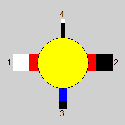
1 |
Medium inlet |
|
|
2 |
Medium outlet |
|
|
3 |
Drain |
|
|
4 |
Control inlet for extraction ratio (as M) |
|
General User Input Values Physics Used Displays Example
Component 19 is used for draining wet steam. It is ineffective for pure water (X=0) or pure steam (X=1).
This component can be used with fluid inlet
• steam
• water
• Two-phase fluid, liquid
• Two-phase fluid, gaseous
The inlet fluid is water, then this component can also be used for steam separation.
For draining other fluids (e.g. fuels), the component 54 (dryer) is available.
The degree of draining is defined by the specification value M3M1W. The entire moisture is drained when M3M1W=1. Then, the steam flow is saturated steam. This can be necessary, if pure wet steam is required for the process.
M3M1W offers three possibilities for interpreting the degree of draining. The specification value FSPEC defines, which of these possibilities is used:
For FSPEC = 0, M3M1W implies the relative decrease of the actual moisture.
For FSPEC = 1, M3M1W implies the mass ratio of the separated water to the water in the inlet.
For FSPEC = -1, Specification M3 from the outside
Example: 100 kg/s wet steam is present with a steam content of 90%. The flow at the inlet thus comprises of 90 kg/s steam and 10 kg/s liquid water. For M3M1W, 80% is entered.
For FSPEC = 0, the calculation is done as follows:
The relative moisture is to be reduced by 80%. For a steam content of 90%, the percentage of water at the inlet is 10%. Therefore, it must be reduced by 80% to 2%. This corresponds to a steam content of 98% at the outlet. The calculation shows that for this 8.167 kg/s of water must be extracted. Thereafter, 1.833 kg/s of water remains, which leads to a steam content of 90 / 91.833 = 0.98 at the outlet.
In case of FSPEC = 1, the calculation is done as follows:
From the 10 kg/s water in the inlet flow, 80% is to be separated. Thus, 2 kg/s remains. The steam content at the outlet is then 90 / 92 = 0.978.
It is also possible to leave the field M3M1W empty. This makes it possible to specify the draining mass flows from outside (e.g. through a measurement point).
Logic inlet (Connection point 4) for controlling component properties
(see also : Editing components --> Ports)
To make component properties like efficiencies or heat transfer coefficients (variation quantity) accessible from the outside (for control or reconciliation) it is possible to place the respective value on an auxiliary line as an indexed measured value (specification value FIND). In the component, the same index must then be entered as specification value IPS.
It is also possible to place these values on a logic line that is directly connected to the component (please see FVALM3M1W=2, Variation variable: M3M1W, Dimension: Mass flow).
The advantage is that the allocation is now graphically visible, and errors (e.g. when copying) are thus avoided.
The activation of this logic line can also be made conditional on the mode of calculation. This way, this feature can also be used for designs without having to switch manually all the time.
For this, the flag FVALM3M1W features the settings
This option is available for Components 2, 6, 8, 13, 18, 19, 23, 24, and 94.
Automatic Transfer
As with many other components, for Components 19 now applies: if a component property (here the Water extraction factor M3M1W ) is specified via a logic connection (here Pin 4, FVALM3M1W must be set to 2), this value is transferred to the respective specification value (here M3M1W ) in the design case.
To be able to suppress this transfer in a design calculation or to enforce it in an off-design calculation, a flag FMODE as it exists in most other components has been added for both
components. However, “blue” values do not exist here.
Note :
For this component there are two options for interpreting the drain factor:
If the discharged drain mass flow is specified from the outside (FSPEC=-1), in M3M1W the value that corresponds to the reduction of the water content at the outlet will be entered as this is also the default setting of the component.
|
FMODE |
Flag for calculation mode Design/Off-design Expression =0: like global in model =1: Local off-design, i.e. always off-design calculation mode, even in case of global design = -1: local design |
|
FVALM3M1W |
Validation of the degree of humidity extraction Like in Parent Profile (Sub Profile option only) Expression = 0: given by the specification value M3M1W (fixed), without validation = 1: (Deprecated) given by the pseudo measurement point IPS (can be validated) |
|
FSPEC |
Interpretation of M3M1W: Like in Parent Profile (Sub Profile option only) Expression = 0: Reduction of liquid water content at outlet = 1: Extracted mass fraction from inlet water =-1: M3 given from outside |
|
M3M1W |
Ratio of the mass flows: M3/M1 (according to FSPEC) |
|
IPS |
Index for pseudo measurement point |
Generally, all inputs that are visible are required. But, often default values are provided.
For more information on colour of the input fields and their descriptions see Edit Component\Specification values
For more information on design vs. off-design and nominal values see General\Accept Nominal values
|
||||||
 |
Display Option 1 |
Click here >> Component 19 Demo << to load an example.