
EBSILON®Professional Online Documentation


|
Line connections |
|
|
|
1 |
Medium inlet |
|
|
2 |
Medium outlet |
|
|
3 |
Branch |
|
|
4 |
Control inlet for distribution ratio (as M) |
|
General User Input Values Physics Used Displays Example
The outlet of connection 3 is defined as a relative value M3/M1. Connection 2 gets the remaining flow.
This component has been enhanced for mechanical shafts and electric lines (Q1 is given). Switching the calculation mode is no longer carried out due to a flag, but due to the line type. In case of shafts and electric lines, the energy split ratio is also specified by the input variable M3/M1.
Limitation M3MAX
The new specification value M3MAX allows to limit the mass flow of the splitter. If a mass flow greater than M3MAX results from the splitting ratio, the splitting ratio will be reduced so far that the mass flow of the splitter equals M3MAX. The splitting ratio that is actually used will be displayed in the result value RM3M1.
M3MAX can also be used
- for mechanical shafts and
- electric lines.
In this case, the desired maximum power of the shaft and electric line respectively has to be entered at M3MAX.
For accelerating the convergence, a flag FSPECM has been added to this component (as in Component 60).
It allows specifying in advance on which streams the mass flow is defined. There are the following options for this:
Specification of two mass flows (i.e. without specifying the splitting ratio):
Specification of one mass flow and the splitting ratio:
Logic inlet (Connection point 4) for controlling component properties
(see also : Editing components --> Ports)
To make component properties like efficiencies or heat transfer coefficients (variation quantity) accessible from the outside (for control or reconciliation) it is possible to place the respective value on an auxiliary line as an indexed measured value (specification value FIND). In the component, the same index must then be entered as specification value IPS.
It is also possible to place this value on a logic line that is directly connected to the component (please see FVALM3M1=2, Variation variable: M3M1, Dimension: Mass flow).
The advantage is that the allocation is now graphically visible, and errors (e.g. when copying) are thus avoided.
The activation of this logic line can too be made conditional on the mode of calculation. This way, this feature can also be used for designs without having to switch manually all the time. For this, the flag FVALM3M1 features the settings
This option is available for Components 2, 6, 8, 13, 18, 19, 23, 24, and 94.
Automatic Transfer
As with many other components, for Components 18 applies: if a component property (here the splitting ratio M3M1 ) is specified via a logic connection (here Pin 4, where FVALM3M1 has to be set to 2), this value is transferred to the respective specification value (here M3M1 ) in the design case.
To be able to suppress this transfer in a design calculation or to enforce it in an off-design calculation, a flag FMODE as it exists in most other components has been added for both components. However, “blue” values do not exist here.
Distribution of the currents on electric lines
It is possible to have the distribution of the currents on electric lines calculated from the resistances or impedances of the two sub-legs.
To do so, the flag FSPECM has to be set to 109 (“Distribution according to impedances of the outlet branches“).
The calculation, however, can only take place if the information on the impedance of the legs is present on both outlet legs. As long as this is not (yet) the case (see Types of streams (pipes)), a distribution of the power output is effected according to specification value M3M1.
As the automatic mechanism for determining the leg resistance only considers the innermost level (see Types of streams (pipes)), it is possible to add another resistor via the logic pin (4). To do so, Pin 4 of Component 18 has to be connected to the electric line that is located downstream of the corresponding mixer. This ensures that the resistance of the residual leg (downstream of the mixer) is considered in the calculation of the total resistance of the superordinate leg (on which the inlet line of the Component 18 is located).
|
FMODE |
Flag for local calculation mode = 0: GLOBAL = 1: Off-design mode = -1: Local Design mode |
|
FSPECM |
Flow handling (mass flow for material streams, power for shafts and electric streams = 0: Any 2 given = 23: M2 and M3 specified =100: M1 or M2 or M3 specified |
|
FVALM3M1 |
Validation of the distribution ratio = 0: Default value used M3M1, without validation = 1: (Deprecated) given by the pseudo measurement point IPS (can be validated) |
|
M3M1 |
Ratio of the mass flows: M3/M1 |
|
M3MAX |
Maximum branch flow (optional) |
|
IPS |
Index for pseudo measurement point |
Generally, all inputs that are visible are required. But, often default values are provided.
For more information on colour of the input fields and their descriptions see Edit Component\Specification values
For more information on design vs. off-design and nominal values see General\Accept Nominal values
|
All cases |
||
|
P2 = P1 T2 = T1 H2 = H1 P3 = P1 T3 = T1 H3 = H1 M3 = M1 * M3M1 then M3 = M3MAX M2 = M1 - M3 Q3 = M3 * H3 Q2 = Q1 - Q3 NCV2 = NCV1 NCV3 = NCV1 |
||
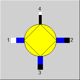 |
Display Option 1 |
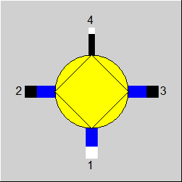 |
Display Option 2 |
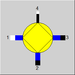 |
Display Option 3 |
Click here >>Component 18 Demo<< to load an example.