EBSILON®Professional Online Documentation


|
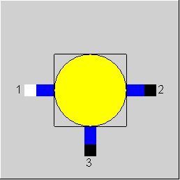
Line connections |
|
|
|
1 |
Fluid inlet |
|
|
2 |
Fluid outlet |
|
|
3 |
Branch (mass flow according to the characteristic) |
|
General User Input Values Characteristic Lines Physics Used Displays Example
The secondary outlet (connection 3) needs a characteristic line defined as default, so that the outlet is defined relative to the primary outlet.
The design behaviour of this component has been adapted to that of the other Ebsilon components. The set value M1N is no longer used as an input in the design case, but instead the char line at M1/M1N=1 will be used to determine the split ratio. The component can also be set to the mode local off-design and local design.
This component has been enhanced for mechanical shafts and electric lines. Switching the calculation mode is no longer carried out due to a flag, but due to the line type. A new variable value Q1N has been introduced that is used in the case of both line type variants in off-design. In design mode, the M1/M1N char line at M1/M1N=1 is used to determine the split ratio Q3/Q1.
|
FADAPT |
Flag for adaption polynomial / adaption function =0: Not used and not evaluated =1: Correction [M3= ADAPT*char line*M1N] =2: Replace [M3= ADAPT *M1N] =1000: Not used but ADAPT evaluated as RADAPT (Reduction of the computing time) =-1: Correction [M3= EADAPT*char line*M1N] =-2: Replace [M3= EADAPT *M1N] =-1000: Not used but EADAPT evaluated as RADAPT (Reduction of the computing time) |
|
EADAPT |
Adaptation function |
|
FMODE |
Calculation mode =0: GLOBAL =1: local off-design |
|
M1N |
Inlet mass flow (nominal) |
|
Q1N |
Inlet power (nominal) |
The parameters marked in blue are reference quantities for the off-design mode. The actual off-design values refer to these quantities in the equations used.
Generally, all inputs that are visible are required. But, often default values are provided.
For more information on colour of the input fields and their descriptions see Edit Component\Specification values
For more information on design vs. off-design and nominal values see General\Accept Nominal values
|
Characteristic line: Mass flow branching M3/M1N=f(M1/M1N) |
|
X-Axis 1 M1/M1N 1st point |
|
All cases |
||
|
P2 = P1 T2 = T1 H2 = H1 P3 = P1 T3 = T1 H3 = H1 M3 = f(M1/M1N) * M1N from characteristic line M2 = M1 - M3 Q2 = M2 * H2 Q3 = M3 * H3 |
||
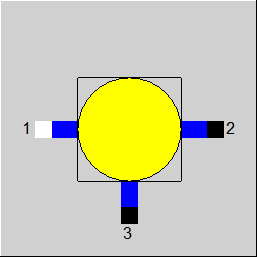 |
Display Option 1 |
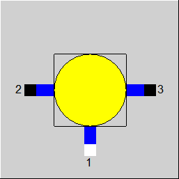 |
Display Option 2 |
Click here >>Component 17 Demo<< to load an example.