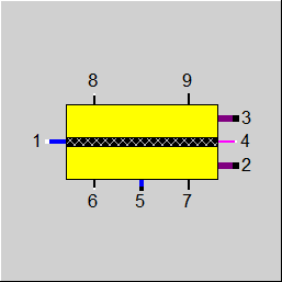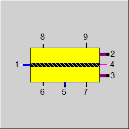

|
Line connections |
|
|
|
1 |
Water inlet |
|
|
2 |
Hydrogen outlet |
|
|
3 |
Oxygen outlet |
|
|
4 |
Electric power inlet |
|
|
5 |
Water purge outlet |
|
|
6 |
Heating inlet |
|
|
7 |
Cooling outlet |
|
|
8 |
Control inlet |
|
|
9 |
Data outlet |
|
General User Input Values Characteristics Lines Physics Used Displays Example
Component 167 represents an electrolysis cell.
|
FTYPE |
Flag for the fuel cell electrolyte type: =0: O-- transport (SOEC) =1: H+ transport (e.g. PEM), saturated gas at both outlets =2: OH- transport (e.g. AEC) |
|
CELLAREA |
Cell Area |
|
NCELLSPERSTACK |
Number of cells per stack |
|
NSTACKS |
Number of Stacks |
|
TEMP |
Operating Temperature |
|
FCURRENT |
Flag for cell current settings: =0: Use value CURRENT =1: Set by port 8 M |
|
CURRENT |
Cell Current |
| PURGEFRAC | |
|
FLOSSES |
Flag for electrical losses method: =0: Use curve CUI and reference fluid concentrations =1: Use data for ohmic and activation losses |
|
AN_H2_REF |
Anode reference H2 molar concentration |
|
AN_H2O_REF |
Anode reference H2O molar concentration |
|
CAT_O2_REF |
Cathode reference O2 molar concentration |
|
CAT_H2O_REF |
Cathode reference H2O molar concentration |
|
T_REF |
Reference Temperature |
|
P_REF |
Reference Pressure |
|
FOHMICLOSSES |
Flag for ohmic losses: =0: Set conductivities =1: Overall definition =2: Detailed layer definition |
|
SIGMA_I |
Ionic coductivity per area |
|
FSIGMA_I |
Flag for ion conductivity definition: =0: Sigma=K/T*exp(-Ea/(RT)) =1: Sigma=K*exp(-Ea/(RT)) |
|
K_SIGMA_I |
Ion conductivity K |
|
EAR_SIGMA_I |
Ion conductivity Ea/R |
|
EL_D |
Electrolyte thickness |
|
EL_FSIGMA_I |
Flag for electrolyte ion conductivity definition: =0: Sigma=K/T*exp(-Ea/(RT)) =1: Sigma=K*exp(-Ea/(RT)) |
|
EL_K_SIGMA_I |
Electrolyte ion conductivity K |
|
EL_EAR_SIGMA_I |
Electrolyte ion conductivity Ea/R |
|
CAT_D |
Cathode thickness |
|
CAT_FSIGMA_E |
Flag for cathode electron conductivity definition: Expression =0: Sigma=K/T*exp(-Ea/(RT)) =1: Sigma=K*exp(-Ea/(RT)) |
|
CAT_K_SIGMA_E |
Cathode electron conductivity K |
|
CAT_EAR_SIGMA_E |
Cathode electron conductivity Ea/R |
|
AN_D |
Anode thickness |
|
AN_FSIGMA_E |
Flag for anode electron conductivity definition: =0: Sigma=K/T*exp(-Ea/(RT)) =1: Sigma=K*exp(-Ea/(RT)) |
|
AN_K_SIGMA_E |
Anode electron conductivity K |
|
AN_EAR_SIGMA_E |
Anode electron conductivity Ea/R |
|
IC_D |
Interconnect thickness |
|
IC_FSIGMA_E |
Flag for interconnect electron conductivity definition: =0: Sigma=K/T*exp(-Ea/(RT)) =1: Sigma=K*exp(-Ea/(RT)) |
|
IC_K_SIGMA_E |
Interconnect electron conductivity K |
|
IC_EAR_SIGMA_E |
Interconnect electron conductivity Ea/R |
|
FACTLOSS |
Flag for activation losses calculation mode: =0: No activation losses =1: Butler Volmer equation |
|
AN_ACT_K |
Anode K [Jref=yH2*yH2O*K*exp(-Ea/(R*T))] |
|
AN_ACT_EA |
Anode Ea [Jref=yH2*yH2O*K*exp(-Ea/(R*T))] |
|
CAT_ACT_K |
Cathode K [Jref=pow(yO2,0.25)*K*exp(-Ea/(R*T))] |
|
CAT_ACT_EA |
Cathode Ea [Jref=pow(yO2,0.25)*K*exp(-Ea/(R*T))] |
|
CDRAGH2O |
Electro-osmotic net drag coefficient (nH2O/nH+) (PEM only) |
|
FXOH2 |
Flag for H2 Crossover calculation: =0: Use Value XOH2 =1: Use charline CXOH2 =2: Use expression EXOH2 |
|
XOH2 |
Crossover Fraction H2 from total H2 produced |
|
EXOH2 |
Expression for Crossover Fraction H2 |
|
FXOO2 |
Flag for O2 Crossover calculation: =0: Use Value XOO2 =1: Use charline CXOO2 =2: Use expression EXOO2 |
|
XOO2 |
Crossover Fraction O2 from total O2 produced |
|
EXOO2 |
Expression for Crossover Fraction HO |
|
FDEGRADATION |
flag for degradation Mode: =0: No degradation =1: Use Value AREAFRACTION =2: Use charline CDEGRADATION =3: Use expression EAREAFRACTION |
|
AREAFRACTION |
Active Area Fraction |
|
EOHOURS |
Equivalent Operating Hours |
|
EAREAFRACTION |
Expression for active area fraction |
The parameters marked in blue are reference quantities for the off-design mode. These are calculated and entered here during the design calculation of EBSILON®Professional.
Generally, all inputs that are visible are required. But, often default values are provided.
For more information on colour of the input fields and their descriptions see Edit Component\Specification values
For more information on design vs. off-design and nominal values see General\Accept Nominal values
|
NAME |
X |
Y |
|
CUI |
Current density |
Voltage |
|
CDEGRADATION |
Equivalent operating hours |
Active area fraction |
|
CXOH2 |
Current density |
H2 Crossover fraction |
|
CXOO2 |
Current density |
O2 Crossover fraction |
|
PEL |
Electrical Power |
|
U |
Voltage |
|
I |
Current |
|
ENERGYCON |
Specific energy consumtion per kg H2 |
|
AREA |
Total area |
|
ADEGRAD |
Effectve area degradation |
|
AREA_EFF |
Effectve area |
|
NCELLS |
Total number of cells |
|
PELCELL |
Cell power |
|
UCELL |
Cell voltage |
|
ICELL |
Cell current |
|
JCELL |
Cell current density (also on Port 9 H) |
|
SIGMA_I_CELL |
Ionic coductivity per area |
The thermodynamic model is similar to the fuel cell (Component 163) in the reverse direction. The model is is zero-dimensional, i.e. there is no temperature profile or concentration profile between inlet and outlet. The temperature is considered to be constant and for the concentrations an average between inlet and outlet is taken.
The model allows different level of details for the current-voltage characteristic of the stack:
- user defined curve
- set the overall conductivity for 1/R1
- set temperature dependent overall conductivity for 1/R1
- set temperature dependent conductivites for each layer and calculate R1
Emax will be calculated with the Nernst-equation. For the reaction
(Ox) a A + b B + ... <=> c C + d D + ... (Red)
the potential E for a temperature T can be calculated by
Emax(T) = E0 - (RT)/(zF)*ln((aCc*aDd)/(aAa*aBb))
E0 = ΔG0/(RT)
| R1 | Overall ohmic losses |
| A, B, C, D | Component A,B,C,D in the reaction |
| a,b,c,d | Stoechiometric coefficients of the components in reaction |
| E0 | reference potential |
| Emax(T) | Current potential at temperature T for given activities of A,B,C,D |
| aA, aB, aC, aD | activities of components A,B,C,D |
| ΔG0 | Gibbs free energy of the reaction at reference conditions (activity=1, p=pref) |
| z | electrons taking part in the redox reaction |
| F | Faraday constant |
| R | Gas constant |
| T | Temperature |
If FLOSSES is set to curve mode, all losses are derived directly from the curve. for a given current density a curve lookup will be made and via the Nernst-equation, Emax for the reference fluid is calculated. The difference is considered as the losses to apply at current conditions
In non-curve mode, Emax will be reduced by ohmic-losses, activation-losses and crossover-losses, if desired
The activation losses will be calculated by the Butler-Volmer-equation for the anode and cathode side.
The ohmic lossses will be calculated according to the setting of FOHMICLOSSES. If temperature dependent behavior is selected, an arrhenius formulation for the conductivity is used.
The crossover lossses allow modeling the migration of H2 and O2 over the electrolyte. Additionally for PEM a water drag coefficient can be specified, which allows to model the migration of water in the electric field over the electrolyte.
Degradation is modeled by reducing the active stack area, which results in an increase of current density and therefore an increase of the losses. The reduction of the active area is modeled with a characteristic curve CDEGRADATION which models equivalent operating hours vs. active area fraction
|
H4 = Pel |
Electrical Power |
|
P4 = U |
Voltage |
|
M4 = 0 |
DC |
|
P1 = P2 = P3 = P5 |
|
|
M5 = m_purge |
purge |
|
M1 - M2 = m_O2 |
H2 production (SOFC type only) |
|
M3 - M2 = m_O2 - (m_H2+m_excess) |
O2 production balance |
|
M2 = m_H2 |
H2 production (PEM and OH- types only) |
|
M1 = m_H2 + m_O2 + m_purge |
Water feed (PEM and OH- types only) |
Kurzweil, Dietlmeier, Elektrochemische Speicher, Springer Vieweg (2018)
 |
Display Option 1: Electrolysis Cell |
 |
Display Option 2: Electrolysis Cell |
Click here >> Component 167 Demo << to load an example.