
EBSILON®Professional Online Documentation


|
Line Connections |
|
|
|
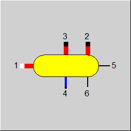
1 |
Main inlet |
|
|
2 |
Main outlet |
|
|
3 |
Steam outlet |
|
|
4 |
Liquid phase extraction outlet |
|
|
5 |
Averaged liquid volume fraction (liquid level) during the time step |
|
|
6 |
Coupled thermal heat inlet |
|
General User Input Values Physics Used Characteristic Lines Results Displays Example
This component uses identical physical algorithms as Component 119 (Indirect Storage). In contrast to Component 119, Component 160 enables an explicit specification of the modes of operation (see flag FOMOD):
It is important that the fluid in the storage system has a correlation between the fluid pressure and the specific volume/density of the fluid and that this correlation can be described by the corresponding material table. Hence the name "Storage for compressible fluids".
Component 160 also enables a correct treatment of the two-phase state and the separate discharging of the liquid and the gaseous phase (Pins 3 and 4).
Thus it is possible to use Component 160 for e.g. the following applications:
The use of Pins 2, 3, and 4 depends on the type of fluid and on the respective material table respectively. If the modelled fluid is only in the gaseous phase (e.g. air), only the use of Pin 2 makes sense. In this case, the fluid stored in Component 160 will exit via Pin 2 in unchanged state. If the modelled fluid is only in a two-phase state (e.g. water/steam), the use of Pins 3 and 4 makes sense. In this case, the liquid and the gaseous phase are separated and can be extracted from the storage system via Pin 3 and 4 respectively. At Pin 5, the volume fraction of the liquid phase is displayed as mass flow and can thus be used for the closed-loop control.
If the flag FINST has the value 1 (steady-state solution), the component will set the enthalpy values and the pressure values at the outlet lines to be identical with the enthalpy at the inlet (PIN 1). In the case of FINST=1, the component CANNOT ensure adherence to the steady-state mass and energy balance because the mass flows at the pins have to be specified by the user. The mode FINST=1 only serves to topologically include the component into the model in the case of the steady-state simulation. The transient charging and discharging processes where the transient mass and energy balances are adhered to MUST NOT be calculated in the mode FINST=1.
If FENTHFL=0, you can specify the value HFLSTART (start value for the fluid enthalpy in the storage tank). This results in the start value for the fill level of the storage tank for 2-phase media (e.g. steam gradient storage tank).
Alternatively, FENTHFL=1 can be used to specify the start value for the fill level of the 2-phase medium in the storage tank. In this case, the value XFLSTART (start value for liquid volume fraction - fill level) is used directly, from which the corresponding fluid enthalpy results with the specified pressure PFLSTART.
The use of XFLSTART makes no sense for pure gas storage tanks.
|
FINST |
Flag: Determination of transient calculation modes = 0: transient solution according to time series table |
|
FINIT
|
Flag: Initializing state =0: Global, which is controlled via global variable "Transient mode" under Model Options =1: First run -> Initializing while calculating steady state values |
|
FALGINST
|
Flag: Determination of transient calculation algorithms |
|
FOMOD
|
Flag: Operation mode (not relevant for initialization) |
|
FINPR |
Flag: Inlet pressure handling (not relevant for FINST=1, FINIT=1) |
|
ASTO |
Heat exchanging area of storage |
|
MSTO |
Mass of storage |
|
VFLUID |
Volume of fluid |
|
THISO |
Thickness of insulation |
|
MRINPART |
Ratio of internal parts to wall mass |
|
FMAT |
Flag: Storage wall material Material Properties of Steel =-1 : Properties calculated by Kernel expression ERHO, ELAM, ECP |
|
ERHO |
Function for material density |
|
ELAM |
Function for material heat conductivity |
|
ECP |
Function for material heat capacity |
|
LAMISO |
Heat conductivity of insulation |
|
FTTI |
Flag: Handling of temperature during time interval |
|
FTSTEPS |
Flag: Specification of (sub-) time steps =1: By specification value TISPEP |
|
ISUBMAX |
Maximum number of time sub steps for initialization |
|
IERRMAX |
Maximum allowed error for initializing step |
|
TISTEP |
Time step |
|
NRAD |
Number of points in wall-normal direction (max. 30) |
|
TIMESING |
Integration time for single calculation when FINST=2 |
|
FFREQ |
Flag: Frequency of transient calculations |
|
FALPHI
|
Flag: Determination of alpha inside |
|
ALPHI |
Heat transfer coefficient alpha inside (wall to fluid) when FALPHI=1; |
|
EALPHI |
Function for alpha inside |
|
FALPHO |
Flag: Determination of alpha outside |
|
ALPHO |
Outer heat transfer coefficient (to ambient) when FALPHO=0 |
|
EALPHO |
Function for alpha outside |
|
PMIN |
Min Allowed Pressure |
|
PMAX |
Max Allowed Pressure |
|
TMIN |
Lower limit for storage temperature |
|
TMAX |
Upper imit for storage temperature |
|
FSTAMB |
Flag: Definition of ambient temperature |
|
TAMB |
Ambient temperature |
|
FSTARTFL |
Flag: Initial fluid state in storage =0: From PFLSTART, HFLSTART or XFLSTART |
| FENTHFL |
Specification of initial fluid enthalpy in storage =0: use HFLSTART |
| XFLSTART | Initial fluid liquid volume fraction (two-phase storage only) |
|
HFLSTART |
Initial fluid enthalpy |
|
PFLSTART |
Initial fluid pressure |
|
FISTART |
Flag: Specification of the storage start temperature |
|
TIMETOT0 |
Total time at start of calculation (Sum of previous time steps) |
|
TAVBEG |
Averaged caloric temperature of the storage in the beginning of the time step |
|
TAVEND |
Averaged caloric temperature of the storage at the end of the time step |
|
QSTO |
Amount of heat stored during time step (storage wall and fluid) |
|
QAV |
Averaged stored heat flow during the time step (storage wall and fluid QSTO/TIMEINT) |
|
QAVI |
Averaged heat flow from fluid to storage |
|
QAVO |
Averaged heat flow from storage to ambient environment |
|
RALPHI |
Calculated heat transfer coefficient fluid-storage |
|
RALPHO |
Calculated heat transfer coefficient storage-ambient |
|
RMSTO |
Mass of the storage wall |
|
RVFLUID |
Overall fluid volume in the storage |
|
MFLUID |
Overall fluid mass in storage |
|
PFLAV |
Mean fluid pressure |
|
HFLAV |
Mean fluid enthalpy |
|
TFLAV |
Mean fluid temperature |
|
RTAMB |
Ambient temperature |
|
TIMETOT |
Total time at the end of calculation |
The calculation of Component 160 is based on the same algorithms like that of Component 119. It calculates in the mode FSPECM=4, in analogy to Component 119. However, Component 160 has no pipe geometry and thus there is no axial flow direction. Thus the numerical 2-D grid contains only one cell in X-direction. In the wall-normal Y-direction, Component 160 can contain several cells in the case of the Crank-Nicolson-Algorithm. The number of cells is controlled via the flag NRAD. In the case of the combined analytic and numeric method, the storage wall is solved only with one cell also in Y-direction.
The condition of the fluid in the storage system – mass, pressure, internal energy, chemical composition – is determined anew in each time step and is saved as input for the next time step. The new fluid condition results from the previous condition, from the parameters and quantities of the fluids flowing in and out in the current time step as well as from the time step length. The fluid volume of the storage system remains unchanged and thus the pressure in the storage system changes with the change of the specific volume of the fluid, which can e.g. be caused by differences between the mass flows flowing in and out or by the change of the parameters of the fluid flowing in.
The enthalpy at outlet 3, 4 does not equal the current mean enthalpy of the fluid in the storage system. By contrast, these enthalpies are determined from the respective phase states.
Regarding the mass flow specification, Component 160 remains passive and adopts the specified mass flows from Pins 1-4. Only at Pin 5, the volume fraction of the liquid phase is set as mass flow.
The enthalpy H1 is always expected externally. The enthalpies H2, H3, H4 are set to equal the fluid enthalpy or enthalpy of the gas and liquid phase respectively in the storage system.
The pressure P2 equals the fluid pressure in the storage system averaged over the time step. For the pressure P1, there are two modes that are controlled via the flag FINPR. At FINPR=0, Component 160 sets the pressure on the line connected to Pin 1 to equal the fluid pressure in the storage system averaged over the time step. At FINPR=1, Component 160 adopts the pressure from the line connected to Pin 1. In this case, however, the pressure on the line must be at least as great or greater than the fluid pressure in the storage system.
If a thermal heat is coupled from externally (e.g. electrical heating elements inside the storage) it can be modelled using the logical Pin 6 by specifying the corresponding power heat value.
All characteristic lines form a circular buffer. The user doesn´t have to take care of them.
Corresponding to this there are also result arrays.
Specification matrix MXTSTO and result matrix RXTSTO
The matrix MXTSTO is linked to the output field RXTSTO in the same way as the characteristic curves and result arrays mentioned above.
The distribution of the values in the storage and the fluids is stored in both matrices (default matrix MXTSTO for time step t-1 and result matrix RXTSTO for time step t).
For the structure of the matrices, see matrices of component 160.
 |
Display option 1 |
Click here>> Component 160 Demo << to load an example.