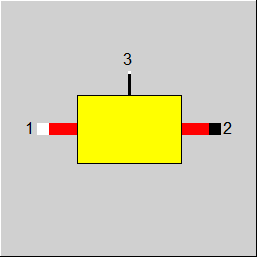

|
Connections |
|
|
|
1 |
Fluid inlet |
|
|
2 |
Fluid outlet |
|
|
3 |
Incoming heat flow |
|
General User Input Values Physics Used Displays Example
Via connection 3 a heat flow can be injected.
This heat flow can, for example, also be specified with control elements (component 12, 39, 69: controller with internal or external values) (FT = 0).
Alternatively (FT= 1, FT = -1), the temperature at output T2 can also be specified.
In the cases FT=1 and FT=-1, the delivered or required heat quantity is applied as enthalpy to the logic line.
Since negative values are permissible on this logic line at connection 3, the heat injection can also be used as heat extraction.
The pressure loss in partial load is limited to 10 times the nominal value, analogous to component 13 (piping). The reason for this is that the pressure losses are too high if the design mass flow is too low. Unlike component 13, the factor 10 is fixed here and cannot be set by a default value (DPDPNMAX). If this limitation becomes active, it is advisable to select a different design point anyway, for example to carry out a local design in the current sub-profile.
|
DP12N |
Absolute pressure loss (nominal) |
|
FMODE |
Flag for calculation mode =0: GLOBAL =1: local off-design |
| FT |
Temperature setting for outlet temperature T2 =0: T2 Calculated from heat balance =1: T2 given by the value of T2SET =-1: T2 preset from outside (via the line at port 2) |
| T2SET | Outlet temperature T2 in case FT=1 |
|
M1N |
Mass flow (nominal) |
The parameters marked in blue are reference quantities for the off-design mode. The actual off-design values refer to these quantities in the equations used.
For more information on colour of the input fields and their descriptions see Edit Component\Specification values
For more information on design vs. off-design and nominal values see General\Accept Nominal values
|
All cases |
||
|
F = (M1/M1N) ** 2 for GLOBAL = Design F= 1.0 DP12 = DP12N * F P2 = P1 – DP12 M2 = M1 NCV2 = NCV1 H2 * M2 = M1*H1 + Q3 T2 = f (P2, H2) |
||
Component Displays
 |
Display Option 1 |
Click here >> Component 16 Demo << to an example.