
EBSILON®Professional Online Documentation


|
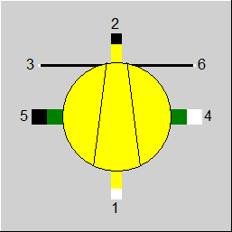
Line connections |
|
|
|
1 |
Medium inlet |
|
|
2 |
Medium outlet |
|
|
3 |
Logical inlet |
|
|
4 |
Shaft inlet |
|
|
5 |
Shaft outlet |
|
|
6 |
Control inlet (currently unused) |
|
General User Input Values Map tables Physics Used Displays Example
Component 159 represents a map-based compressor which models its flow rate vs. pressure rise vs. rotational speed behaviour. The component tries to use the maps from the manufacturer directly without much manual conversion by the user. Maps can be imported via an importer tool, which allows to manually convert a compressor map image to a compressor map table.
The compressor map is represented by (X,Y,Z,EFF) data points with various options for X,Y,Z,EFF. The calculation modes allow to calculate any of X,Y,Z from the two others.
In order to derive the correct dimensionless reduced flow and reduced speed, if used in the settings, it is necessary to set the correct reference properties MW_REF, T_REF, P_REF, Z_REF, K_REF.
If the map is given in terms of mach numbers, it is necessary to set the dimensions DIN and DIMP, in order to be able to calculate actual mach numbers
If the efficiency and pressure rise are given as total to static, it is necessary to set the outlet diameter DOUT, in order to convert between total and static properties.
If performance factors are activated, the following relationships are used:
| EFF = | EFF_from_map_lookup * PFEFF | (FCALC=1,2,3) |
| X = | X_from_map_lookup * PFX | (FCALC=2) |
| Z = | Z_from_map_lookup * PFZ | (FCALC=1) |
| X_used_in_map = | X / PFX | (FCALC=1,3) |
| Z_used_in_map = | Z / PFZ | (FCALC=2,3) |
|
FCALC |
Flag for the calculation mode: =0: Bypass (out=in) |
|
MW_REF |
Inlet reference molecular weight |
|
T_REF |
Reference inlet temperature |
|
P_REF |
Reference inlet pressure |
|
Z_REF |
Reference inlet compressibility factor Zref = Pref*Vref/(R*Tref) |
|
K_REF |
Reference inlet isentropic exponent (k=cp/cv) |
|
F_USE_Z_REF |
Flag for the usage of Z_REF: =0: NO (no usage of Z_REF and Z in the calculation of corrected flow and corrected speed) |
|
DIN |
Inlet diameter |
|
DOUT |
Outlet diameter |
|
DIMP |
Impeller diameter |
|
N_REF |
Reference corrected rotational speed |
| FN_REF |
Flag for shaft speed in IGV mode =0: Emit N_REF as shaft speed |
|
FX |
Flag for X definition: =0: X is corrected flow |
|
FY |
Flag for Y definition: =0: Y is corrected speed |
|
FZ |
Flag for Z definition: =0: Z is pressure ratio |
|
FEFF |
Flag for efficiency Input (map MXCMAP, column 4): =0: set efficiency |
|
FPREFF |
Flag for PR and EFF definition: =0: PR and EFF are total-to-static isentropic |
|
EFFM |
Mechanical efficiency (fraction) |
|
LOSSM |
Mechanical loss (constant) |
|
FPFEFF |
Flag for performance factor efficiency: =0: None |
|
PFEFF |
Performance factor efficiency |
|
EPFEFF |
Expression for performance factor efficiency |
|
FPFX |
Flag for performance factor X (mutually exclusive to FPFZ): =0: None |
|
PFX |
Performance factor X |
|
EPFX |
Expression for performance factor X |
|
FPFZ |
Flag for performance factor Z (mutually exclusive to FPFX): =0: None |
|
PFZ |
Performance factor Z |
|
EPFZ |
Expression for performance factor Z |
The parameters marked in blue are reference quantities for the off-design mode. These are calculated and entered here during the design calculation of EBSILON®Professional.
Generally, all inputs that are visible are required. But, often default values are provided.
For more information on colour of the input fields and their descriptions see Edit Component\Specification values
For more information on design vs. off-design and nominal values see General\Accept Nominal values
|
MXCMAP |
col1=Y |
col2=X |
col3=Z |
col4=EFF or PWR |
Compressor map core table |
|
MXSURGE |
col1=X |
col2=Z |
Surge line limit |
||
|
MXEFFISO |
col1=ID |
col2=X |
col3=Z |
col4=EFF |
Iso efficiency lines. Not used in calculations, only within the importer tool |
|
MXPFEFF |
col1=Y |
col2=X |
col3=PFEFF |
performance factor correction efficiency |
|
|
MXPFX |
col1=Y |
col2=Z |
col3=PFX |
performance factor correction X |
|
|
MXPFZ |
col1=Y |
col2=X |
col3=PFZ |
performance factor correction Z |
|
Q |
Shaft power |
|
RFLOW |
Corrected flow |
|
RSPEED |
Corrected rotary speed |
|
RELRSPEED |
Relative corrected rotational speed |
|
FLOW |
Flow |
|
SPEED
|
Shaft rotary speed
|
|
PR_TT |
Pressure ratio total-total |
|
PR_TS |
Pressure total-static |
|
P1_T |
Inlet pressure total |
|
P1_S |
Inlet pressure static |
|
P2_T |
Discharge pressure total |
|
P2_S |
Discharge pressure static |
|
MCH_AX |
Mach-number axial |
|
MCH_RAD |
Mach-number radial |
|
RIGV |
Inlet Guide Vane Angle (IGV) |
|
EFFI_TT |
Efficiency isentropic total-total |
|
EFFI_TT |
Efficiency isentropic total-static |
|
EFFP_TS |
Efficiency polytropic total-total |
|
EFFP_TT |
Used value of the adjustment polynomial |
|
HDISEN_TT |
Isentropic head total-total |
|
HDISEN_TS |
Isentropic head total-static |
|
VM1 |
Inlet volume flow |
|
RPFEFF |
Performance factor efficiency |
|
VM1 |
Inlet volume flow |
|
RPFX |
Performance factor X |
|
RPFZ |
Performance factor Z |
|
FCALC = 0 |
Bypassmode. |
|
FCALC = 1 |
Calculate Z(X,Y) |
|
FCALC = 2 |
Calculate X(Y,Z) |
|
FCALC = 3 |
Calculate Y(X,Z) |
|
M2 - M1 = 0 |
|
|
M5 - M4 = 0 |
|
|
H2 - H1 = dH |
|
|
H5 - H4 = -M1 * dH * EFFM |
|
|
P2 - pressure_ratio * P1 = 0 (FCALC = 1) M1 = inlet_flow (FCALC = 2) M4 = RPM (FCALC = 3) |
 |
Display Option 1: Compressor |
 |
Display Option 2: Axial Compressor |
 |
Display Option 3: Radial Compressor |
Click here >> Component 159 Demo << to load an example.