EBSILON®Professional Online Documentation


|
Line connections |
|
|
|
1 |
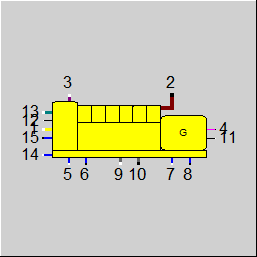
Air inlet |
|
|
2 |
Exhaust outlet |
|
|
3 |
Gas fuel inlet |
|
|
4 |
Power outlet |
|
|
5 |
Heat rejection #A inlet |
|
|
6 |
Heat rejection #A outlet |
|
|
7 |
Heat rejection #B inlet |
|
|
8 |
Heat rejection #B outlet |
|
|
9 |
Heat rejection #C inlet |
|
|
10 |
Heat rejection #C outlet |
|
|
11 |
Logic input |
|
|
12 |
Ambient conditions (logic input) |
|
|
13 |
Diesel fuel inlet |
|
|
14 |
Heat rejection #D inlet |
|
|
15 |
Heat rejection #D outlet |
|
General User Input Values Specification Matrices Using the Library Defining the Operating Mode Physics Used Results Displays Example
Component 153 can be used for modeling gas, diesel or dual fuel reciprocating engines based on OEM performance data compiled in the ENEXSA Reciprocating Engine Library. In order to allow for detailed studies of the integration of the heat rejected from the engine jacket, turbochargers, and lubrication system, the engine cooling cycles are modelled including the respective flow and temperature control schemes for high and low temperature cooling water and the engine oil. Since different manufacturers apply different control philosophies and the same base engine may be optimized for application in power generation only, CHP operation (i.e. maximum overall fuel efficiency with focus on the usage of the cooling cycle), or combined cycle operation (i.e. maximum fuel efficiency with focus on steam generation), a generic base model consisting of multiple heat sources and heat rejection groups has been developed that can be configured to reflect a specific design.
While for the pre-configured data sets the user does not need to interact with this configuration, component 153 may also be used to create or adjust data sets, if measured data or vendor data sheets are available.
|
FCALC |
Flag for engine calculation mode =0: Off (bypass, all connected streams set to zero mass and energy flow) |
|
SMODEL |
Curve set description (from Library) |
|
SVENDOR |
Vendor name (from Library) |
|
FDATASET |
Active curve set (selectable from drop-down list of data sets currently loaded into the component) |
|
FLOAD |
Flag for load definition mode = 0: Load fraction (relative to base load output) |
|
FLOADFRAC |
Flag for source of load target value = 0: Use LOADFRAC |
|
LOADFRAC |
Desired load fraction |
|
FPOWER |
Flag for source of desired generator power = 0: Use POWER |
|
POWER |
Desired generator power |
|
ENGINE DEFINITION |
REFERENCE SITE CONDITIONS |
|
T1N |
Nominal inlet air temperature |
|
ELEVN |
Nominal elevation |
|
ENGINE DEFINITION |
NOMINAL OUTPUT |
|
POWERN |
Nominal generator output |
|
HEATRATEN |
Nominal heat rate |
|
M2N |
Nominal exhaust flow |
|
T2N |
Nominal exhaust temperature |
|
ENGINE DEFINITION |
HEAT SOURCE #i; i = 1...6 |
|
SQi |
Heat source #i name (text string) |
|
FQi |
Flag for definition of heat rejection group of source #i = 0: NONE (OFF) |
|
QiORDER |
Flag for definition of order in selected rejection group = 0: Don't care |
|
QiN |
Nominal duty of heat source #i |
|
ENGINE DEFINITION |
HEAT REJECTION GROUP #x; x = A (ports 5,6), B (ports 7,8), C (ports 9,10), D (ports 14,15); j = 5,7,9,14 (group inlet ports) |
|
SPORTx |
Heat rejection group x description |
|
TjN |
Nominal inlet temperature of group x |
|
FVMODEx |
Flag for definition of flow control mode of group x = 0: Flow set externally |
|
FTMODEx |
Flag for definition of temperature control mode group x = 0: Inlet and exit temperature set externally (calculate Qx) |
|
ISOURCEx |
Flag for definition of location of TVALUEx after source... (for FTMODEx = 4 only) = 1: Source #1 |
|
VMVALUEx |
Desired volume flow (target value for method defined in FVMODEx) |
|
TVALUEx |
Desired temperature (target value for method defined in FTMODEx) |
|
VMMINx |
Limits - Minimum volume flow |
|
VMMAXx |
Limits - Maximum volume flow |
|
TINMINx |
Limits - Minimum inlet temperature |
|
TINMAXx |
Limits - Maximum inlet temperature |
|
TOUTMAXx |
Limits - Maximum exit temperature |
|
|
|
|
FUELTYPE |
Flag for fuel type definition = 0: Gas |
|
LHVMIN |
Minimum fuel LHV |
|
PFOFHRATIO |
Pilot flame heat ratio (for dual fuel operation, fraction of total heat input through diesel fuel) |
|
LOADMIN |
Minimum load fraction |
|
DP2MAX |
Maximum exhaust pressure drop |
|
DERTLO |
Derating below temperature |
|
DERTHI |
Derating above temperature |
|
DERELEVHI |
Derating above elevation |
|
DERHUMHI |
Derating above specific humidity |
|
EMISSION DEFINITION |
|
|
FO2REF |
Reference O2 Mode = 1: Use Internal O2 Reference |
|
O2REFCON |
Reference O2 Concentration (Dry) |
|
FCON |
Specification of COCON/NOXCON (base of fractions) = 0: Volume Fraction |
|
COCON |
Concentration of CO in Dry Exhaust Gas |
|
NOXCON |
Concentration of NOx in Dry Exhaust Gas |
|
NOXSPLIT |
NO-Split (NO/(NO+NO2) (Volume Fraction)) |
Generally, all inputs that are visible are required. But, often default values are provided.
For more information on colour of the input fields and their descriptions see Edit Component\Specification values
For more information on design vs. off-design and nominal values see General\Accept Nominal values
|
MXHC: HC = f (LOAD, T1) |
| Heat consumption as a function of part load fraction and inlet air temperature |
|
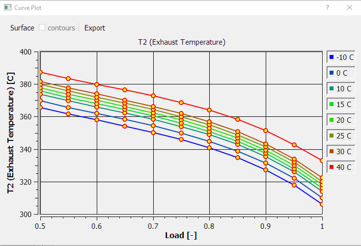
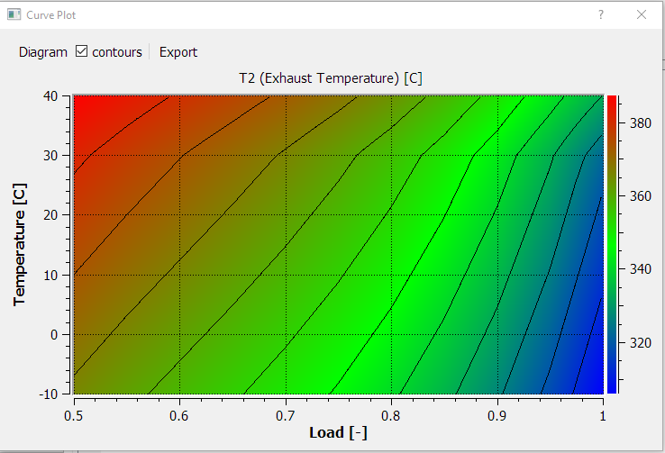
MXT2: T2 = f (LOAD, T1) |
| Exhaust temperature as a function of part load fraction and inlet air temperature |
|
MXM2: M2 = f (LOAD, T1) |
| Exhaust mass flow as a function of part load fraction and inlet air temperature |
|
MXQi: Qi = f (LOAD, T1); i = 1...6 |
| Duty of heat source i as a function part load fraction and inlet air temperature |
|
MXDQxy: DQxy = f (LOAD, T1); x = A,B,C,D; y = A,B,C,D; x ≠ y |
| Shift in duty from heat source x to heat source y as a function part load fraction and rejection group x inlet temperature |
The Reciprocating Engine Library is designed as an add-on to EBSILON and it provides pre-configured data sets of reciprocating engine performance data which – similar to the ENEXSA Gas Turbine Library contained in component 106 – are continuously kept up to date based on information retrieved from the original equipment manufacturers (OEM). The library is licensed by ENEXSA Energy GmbH, but the license is managed through flag 25 of the EBSILON license. If the library is not licensed, component 153 can be used, but only with calculation mode FCALC = 2 (Use local data) in which all performance information must be supplied by the user in the specification values and spec-matrices. If licensed and used in calculation mode FCALC = 1 (Use library data), specification values and spec-matrices remain empty, since all data are read from the library data set. All data can be viewed in the user interface of the Reciprocating Engine Library.
At the first use of the Library as well as for changing to a specific location of data sets, the user can choose the library location through the menu item "File – Select Library Directory" and browse to the location of the data sets. Reciprocating engine data sets have the file extension "*.geb", and the initial release as well as data updates under software maintenance will be distributed to the users in form of compressed ZIP files that can be extracted to any location that provides read access. The library location will be saved with the application, and the program will automatically choose the last library location upon re-start.
With the button “Show Library” the content of the current library location will be shown in a table that can be sorted (by clicking of the respective column header) and filtered (by typing expressions in the row below the column header). Upon mouse-over, tool tips will advise on the filtering options for the respective column.
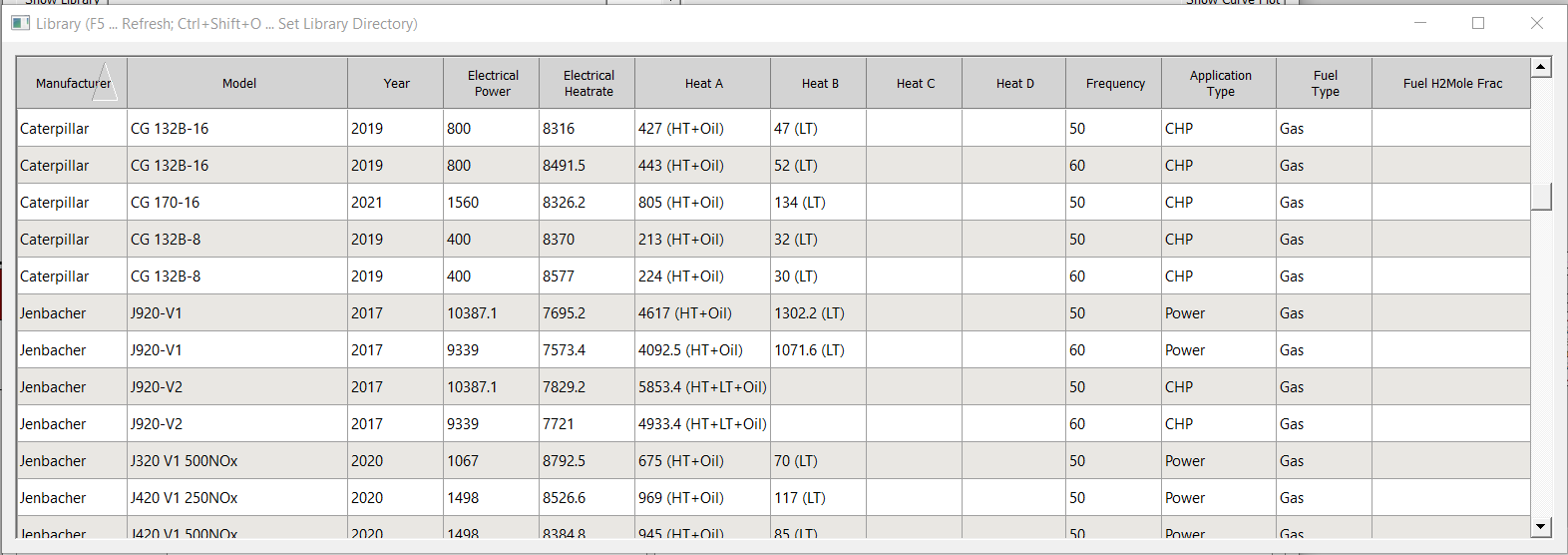
A data set is selected by double-clicking the respective table row.
The following explanations are for information only, since all of the input data will come from the library and no user inputs will be required. Upon confirmation of overwriting the current data, the selected data set will be loaded and can be viewed in the following input tabs of the user interface:
Summary – provides general information about the engine and vendor contact information
Nominal Data – provides nominal performance data and respective reference conditions as well as limits for operation
Heat Rejection – defines the heat sources and heat rejection groups of the engine as well as the control schemes for flow and temperature
Curves – two-dimensional curves describing off-design performance as function of operating parameters
The concept of heat sources and heat rejection groups can be explained comparing the flow scheme shown below with the screen shot of the Heat Rejection tab representing the same configuration.
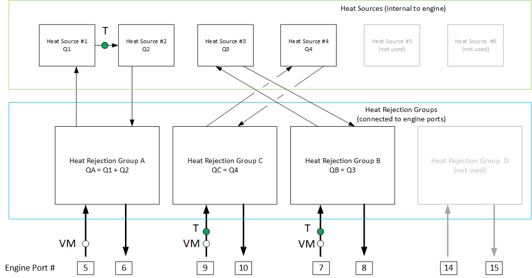
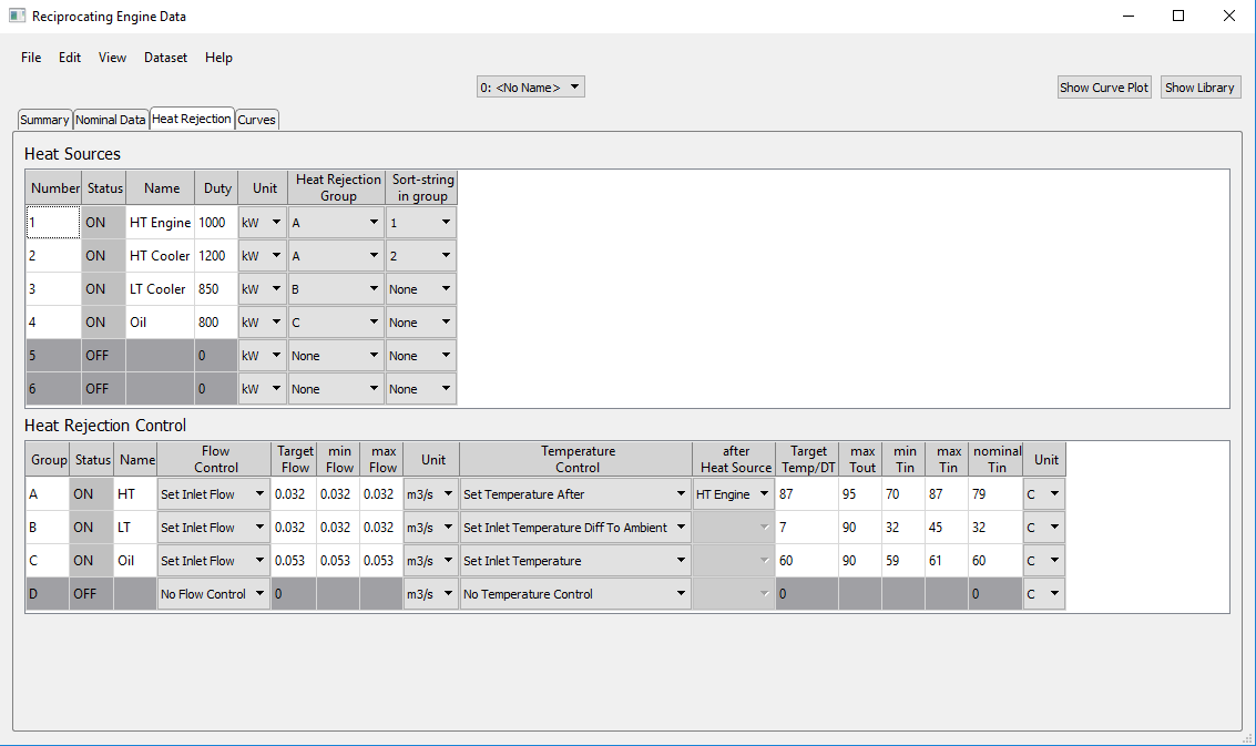
There are up to six heat sources which can be defined to reflect the heat dissipated of the various coolers of the engine: turbocharger intercooler, engine jacket cooler, lubricating oil cooler etc. In the table in the upper section of the Heat Rejection tab, heat sources #1 and #2 (defined as HT Engine heat of 1000 kW at reference conditions and HT Cooler heat of 1200 kW) are combined in Rejection Group A with a sort string #1 = 1 and #2 = 2. This setting reflects the situation in the flow scheme that Heat Rejection Group A collects heat from Heat Source #1 and subsequently from Heat Source #2. The two other heat sources available from the engine are LT Cooler heat (#3, 850 kW, connected to Heat Rejection Group B) and Oil heat (#4, 800 kW, connected to Heat Rejection Group C). There are up to five heat sources available in the generic model, but in this example, only four are required, so Heat Sources #5 and #6 are at status OFF, because they are not connected to a rejection group.
The lower section of the tab contains the settings for flow and temperature control of the heat rejection groups which interface to the ports of the equipment. Please note that – due to the industry convention for reciprocating engines – all liquid flows are defined as volumetric flows and not as mass flows. In our example the inlet flows at ports 5, 7, and 9 are set to a fixed value. Alternatively, the flow control scheme may be set to vary the flow in order to reach a specific exit or inlet temperature. The desired temperature is defined in the Temperature Control section of this table, where temperatures at specific locations are defined for the individual rejection groups. If a group contains several heat sources, the location of the desired temperature may also be defined through the setting “Set Temperature After” in combination with the selection of available heat sources of this group in the next column “after Heat Source”. The setting reflects the temperature definition at the green dot shown between heat sources #1 and #2 in the above flow scheme, and if in addition the inlet flow at port 5 is set (white dot in the scheme) and the individual duties of sources #1 and #2 are set, the heat balance will produce the temperatures at ports 5 and 6.
Important Note: When modeling the integration of the reciprocating engine with external heat exchangers for CHP operation, such desired inlet temperature typically cannot be reached with a single equipment. As in real power plant configurations, the model will have to include redundant back-up coolers (e.g. air coolers modelled with component 127) which will reject the surplus heat to the ambient.
If air coolers are used, the achievable inlet temperature to the engine may be limited by the ambient temperature. For this purpose, the temperature control section also includes the option “Set Inlet Temperature Diff(erence) To Ambient”, as used in our example for the control scheme of Heat Rejection Group B. The information about the current ambient temperature has to be provided through the logic line at port 12. In case of low ambient temperature, this setting may hit the lower boundary of the inlet temperature set as "min Tin", so that the inlet temperature will be kept constant at this value (resulting e.g. in partial bypass or part load operation of the external air cooler).
The effect of operating conditions on the performance of the engine is modelled through two-dimensional curves (matrices) that reflect heat consumption (HC), exhaust temperature (T2), exhaust gas mass flow (M2), and the specified duties of heat sources Q1 - Q6 as a function of part load fraction (parameter X) and inlet suction temperature (Y), as shown for exhaust temperature in the sample screen shot below.
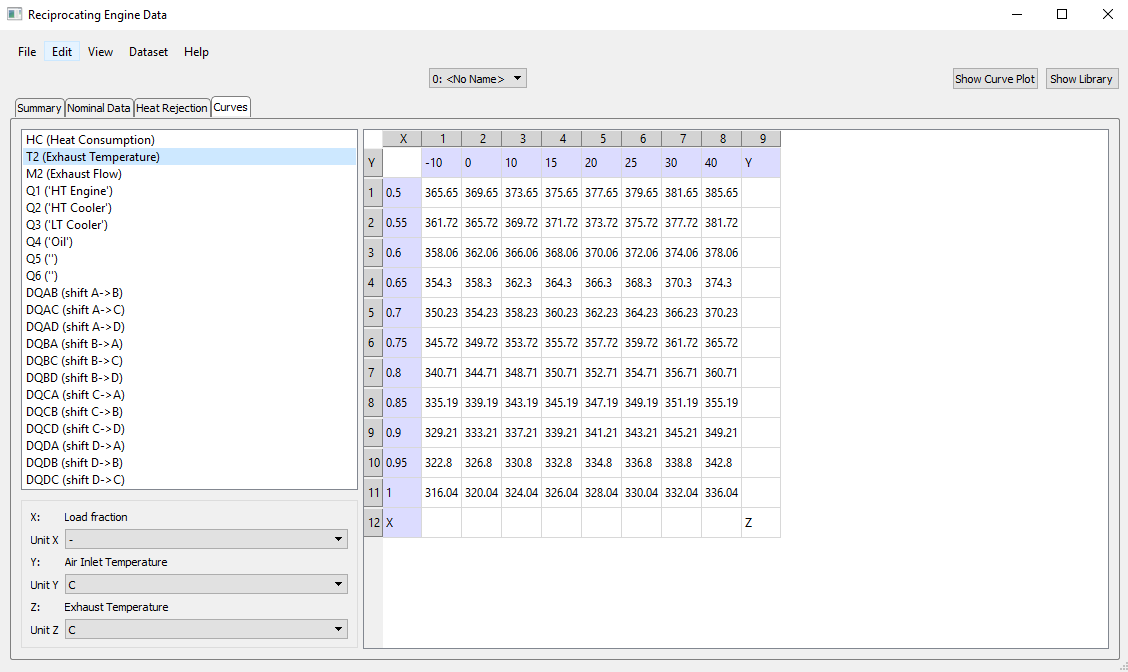
With the button "Show Curve Plot", the data can also be visualized in for of a diagram or surface plot which can also be exported in a suitable graphics format.
In addition, there are matrices DQxy (x,y = A,B,C,D) that allow to define the shift in duty (delta kW from group x to group y) between the individual heat rejection groups as a function of part load fraction and the inlet temperature to the respective group x.
Since an engine data sets is representing an existing equipment design, there are no design calculations for component 153. The only controllable parameter for the user is the power output/load level of the engine. The heat rejected from the engine cooling cycles or contained in the exhaust gas can only be controlled through adjusting the engine load.
Independent of whether the component is set up to use a library data set or local data, the user can choose to define the load mode FLOAD to be based on part load fraction (i.e. as a fraction of the power output at base load) or in absolute numbers as generator output. For both cases, the target value can either be defined as an input value to the engine with the parameters LOADFRAC and POWER, respectively, or the respective target value may be read from the logic line at port 11 which allows for connecting to an external controller. When using generator power output, the target value may also be set externally on the electric line connected at port 4 of the engine.
|
|
||
|
Internal Calculations: |
||
|
|
Power QEL = POWER or LOAD * POWERN Heat consumption HC = POWERN *HEATRATEN/3600 * MXHC(LOAD,T1)/MXHC(1.0,T1N) Exhaust flow M2 = M2N *MXM2(LOAD,T1)/MXM2(1.0,T1N) Exhaust temperature T2 = T2N + MXT2(LOAD,T1) - MXT2(1.0,T1N) Qi = QiN * MXQi(LOAD,T1)/MXQi(1.0,T1N) QX = Σ Q as per group configuration - Σ QXY + Σ QYX resulting M and H at ports 5-10 and 14-15 as per flow and temperature control scheme |
|
The results relevant for the heat balance calculation are displayed in the tab 'Results' of Component 153.
 |
Display Option 1 |
Click here >> Component 153 Demo << to load an example.