
EBSILON®Professional Online Documentation


|
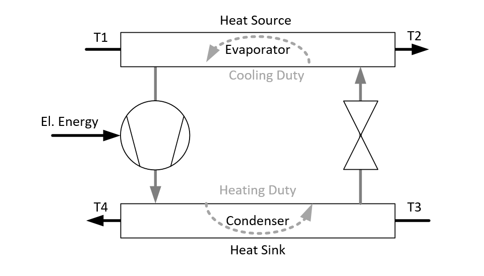
Line connections |
|
|
|
1 |
Heat source inlet |
|
|
2 |
Heat source outlet |
|
|
3 |
Heat rejection inlet |
|
|
4 |
Heat rejection outlet |
|
|
5 |
Power inlet |
|
|
6 |
Condensate outlet |
|
|
7 |
Logic Inlet |
|
General User Input Values Characteristic Lines Specification Matrices Physics Used Example
With component 152, electric chiller, the user can model the performance and power consumption of a chiller system based upon electrically driven compression chillers. The performance (power consumption) calculation is based on curves. Default curves are available as a collection of curves for specific chiller units which are available on the market.
|
FMODE |
Flag to set the calculation mode Design / Off-design =0: Global |
|
FFU |
Switch ON/OFF =0: OFF (heat source inlet = heat source outlet; all other flows = 0) =1: ON |
|
FDES |
Flag to set the chiller design mode =2: Outlet temperature T2 set externally =4: Desired outlet temperature T2 given as T2TARGET |
|
FSIZE |
Flag to set the basis for the unit size =0: cooling duty MXQC (calculate NUNITS and RLOAD < LOAD) =1: heating duty MXQH (calculate NUNITS and RLOAD < LOAD) =2: from T2, LOAD and NUNITS |
|
FCOP |
Flag to set the basis for COP (coefficient of performance) =0: Electrical power (MXQEL) - COP will be calculated relative to cooling duty Q12 =1: Cooling COP (MXCOP) =2: Heating COP (MXCOP) |
|
FOPOD |
Flag to set the operating mode in off-design =2: Desired outlet temperature T2 set externally (calculate NUNITS and RLOAD < LOAD) =4: Desired outlet temperature T2 given as T2TARGET (calculate NUNITS and RLOAD < LOAD) =1: Set NUNITS and partload fraction as LOAD =3: Set NUNITS and partload fraction on logic port 7 as H |
|
LOAD |
Desired partload fraction |
|
T2TARGET |
Desired exit temperature |
|
NUNITS |
Number of active units |
|
DP12 |
Pressure drop between heat source inlet and outlet |
|
DP34 |
Pressure drop between heat rejection inlet and outlet |
|
MINLOAD |
Minimum partload fraction per unit |
|
T1N |
Nominal inlet temperature of the heat source |
|
M1N |
Nominal inlet flow of heat source |
|
M3N |
Nominal inlet flow of heat rejection |
|
V1N |
Nominal specific volume of heat source |
|
V3N |
Nominal specific volume of heat rejection |
|
Q12N |
Nominal cooling duty per unit |
|
DP12N |
Nominal heat source pressure drop |
|
DP34N |
Nominal heat rejection pressure drop |
|
NUNITSN |
Nominal number of units |
The parameters marked in blue are reference quantities for the off-design mode. The actual off-design values refer to these quantities in the equations used.
Generally, all inputs that are visible are required. But, often default values are provided.
For more information on colour of the input fields and their descriptions see Edit Component\Specification values
For more information on design vs. off-design and nominal values see General\Accept Nominal values
|
CPLCOP : COP correction = f (Q12/Q12BASE); Q12/Q12BASE is the part load fraction of the cooling cycle |
|
1 cooling cycle partload fraction 1st point |
|
CT4MAX: maximum T4 = f(T1); maximum heat sink outlet temperature as a function of heat source inlet temperature |
|
X-Axis 1 Heat source inlet temperature 1st point |
|
CT4MIN: minimumT4 = f(T1); minimum heat sink outlet temperature as a function of heat source inlet temperature |
|
X-Axis 1 Heat source inlet temperature 1st point |
|
MXQC: Q12 = f (T1, T4) |
| Cooling duty as a function of heat source inlet temperature and heat sink exit temperature |
|
MXQH: Q34 = f (T1, T4) |
| Heating duty as a function of heat source inlet temperature and heat sink exit temperature |
|
MXQEL: Q5 = f (T1, T4) |
| Power consumption as a function of heat source inlet temperature and heat sink exit temperature |
|
MXCOP: COP = f (T1, T4) |
| Coefficient of performance (COP) as a function of heat source inlet temperature and heat sink exit temperature. The basis for the COP, i.e. if it is relative to the cooling or the heating duty, has to be specified in the parameter FCOP. |
The module carries out mass and energy balances for the two process streams which comprise the heat source and the heat sink. In addition, an overall energy balance provides all relevant duties, such as cooling, heating and electric energy:
Warm Side Duty = Cold Side Duty + Electrical Energy
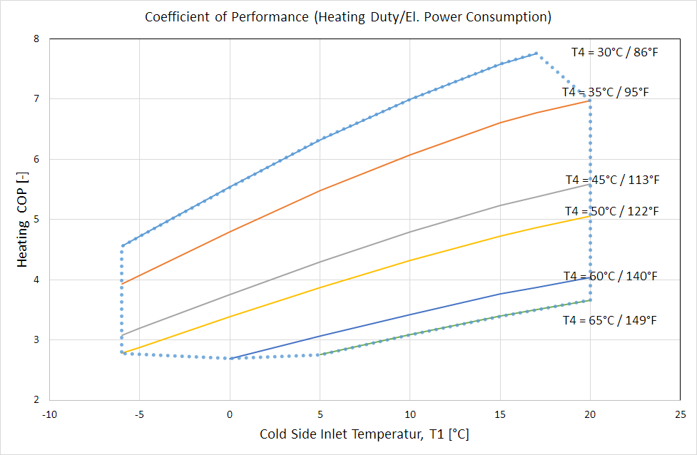
The operation of a compression chiller is characterized by performance maps with boundaries in terms of cold side (heat source) inlet temperature (T1) and the achievable warm side (heat sink) temperature (T4) which is the maximum temperature rise a specific machine can produce. Below diagram shows a typical performance range for an industrial heat pump.
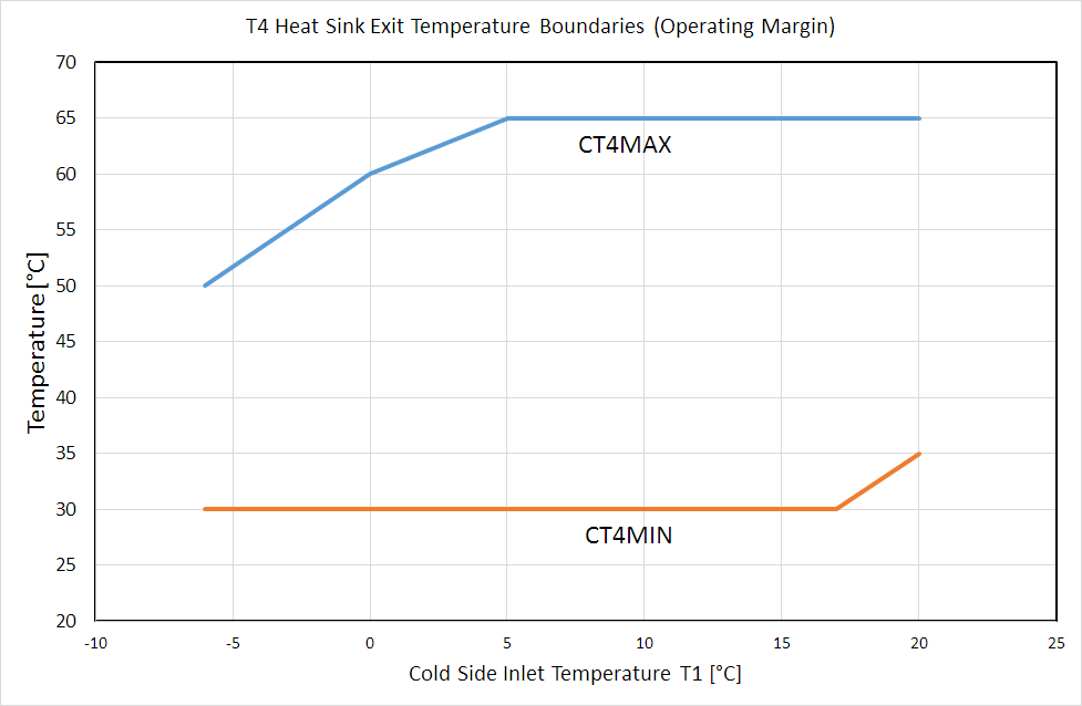
The permissible boundaries are specified in terms of two characteristic lines, which define the maximum possible T4 (CT4MAX) and the minimal required T4 (CT4MIN) for the unit to function properly, as a function of cold side inlet temperature (T1). Below diagram shows the permissible minimum and maximum hot side exit temperature, corresponding to the above performance characteristics. It is the user’s responsibility to provide sufficient mass flow at the heat sink so that the resulting warm side exit temperature remains within these boundaries. If the temperature boundaries are exceeded, the component will issue a warning. Exceeding T4max means the flow 34 needs to be increased, falling below T4min means flow 34 needs to be reduced.
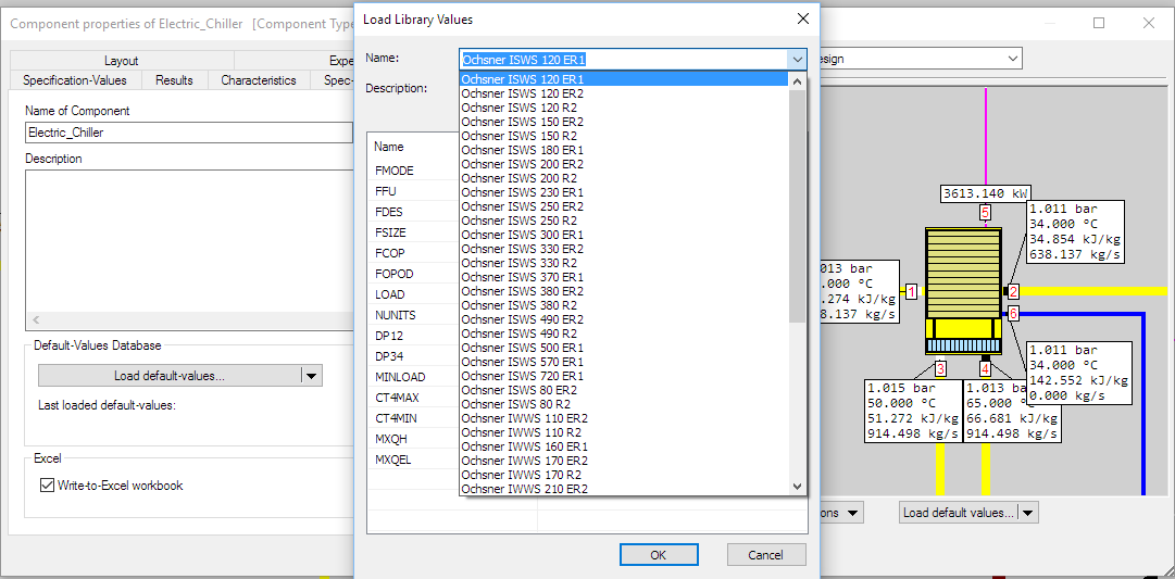
A library of heat pump performance characteristics has been included in the Default-Values Database of component 152. With the command "Load default-values.." in the tab "Basic Properties" the following menu can be activated which lists the default data sets which provide both, specification matrices and corresponding settings for calculation settings, so that the performance data are ready to use.
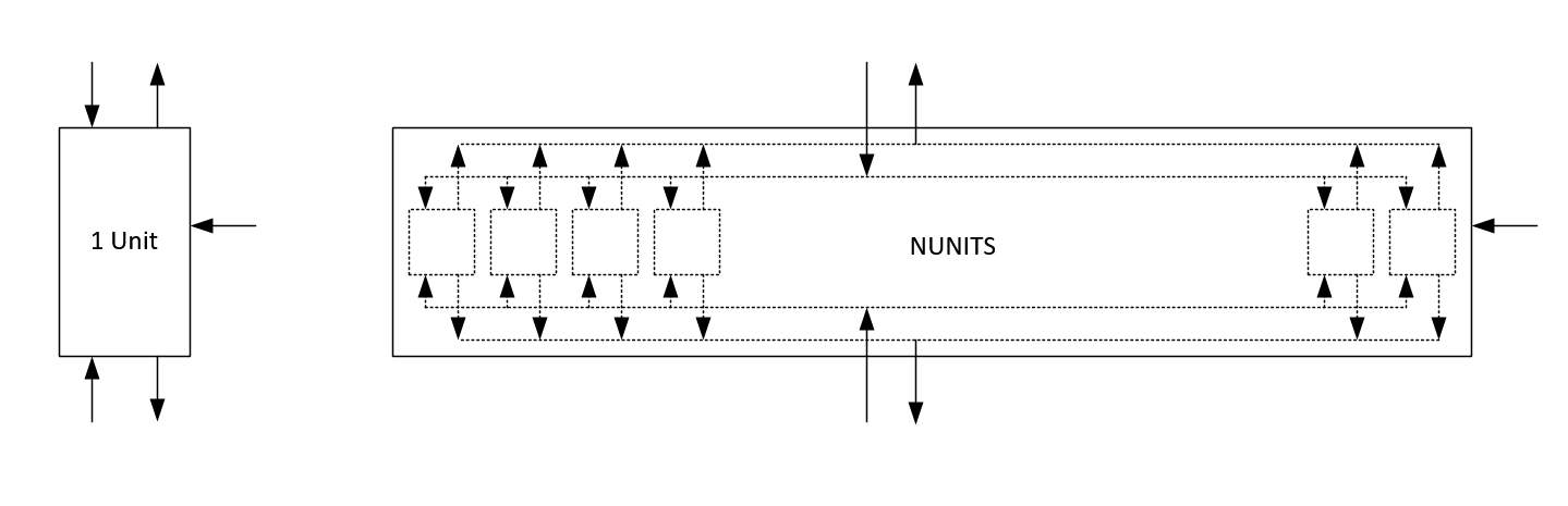
The component can be set up to represent just the chiller units; one chiller unit or any array of equally sized units, of which the number can either be specified by the user, or it can be determined based on a given performance of the chiller unit:
Typically the user will specify the cold side duty of the process through inlet temperature (T1), flow rate (M1) and desired exit temperature (T2) of the main inlet stream (e.g. GT inlet air) which can specified through the method FDES to be set externally or defined by input value T2TARGET. While setting up a model, it is the user’s responsibility to adjust warm side flow rate so that the resulting exit temperature (T4) remains within permissible boundaries. The model offers several ways to specify the chiller performance. These are the following performance maps with the parameters cold side inlet temperature T1 and warm side exit temperature T4, in form of two dimensional specification matrices:
(1) Cold-Side Duty (MXQC:Q12)
(2) Warm-Side Duty (MXQH:Q34)
(3) Electric Power Consumption (MXQEL:Q5)
(4) Warm-Side Coefficient of Performance (MXCOP:COP, FCOP=2)
(5) Cold-Side Coefficient of Performance (MXCOP:COP, FCOP=1)
Performance maps (1)-(3) are given in absolute units (kW, BTU/h) and fit the capability of a specific physical unit. Adjustment to a desired heating or cooling duty in design mode will be achieved by calculating the necessary number of units. For using unit specific performance maps (1)-(3) it is required to use two matrices for providing a full balance: either (1) or (2) in combination with either (3) or (4) or (5) . The respective combination can be defined in the input vales FSIZE (basis for unit size) and FCOP (basis for COP). If the electrical consumption is calculated directly from the matrix MXQEL (i.e. FCOP = 0), the result value for the coefficient of power RCOP will be based on the cold side duty Q12.
The calculation flow is as follows: Using T1 and T4 the model looks up performance map (1) or (2) (depending on the specification FSIZE) and looks up performance map (3), or (4), or (5) depending on FCOP. With that the electric power consumption can be calculated, and by means of balance the other corresponding duty.
Performance maps (4) and (5) are dimensionless. These can be used, if no unit specific data of a chiller are available. The model contains a reasonable default performance map. The user has to select FSIZE = 2 and define the number of units in operation with the specification value NUNITS, and based on the default map the unit will be sized in terms of nominal cooling duty Q12N. In such case the calculation procedure is as follows: Depending which process side (cold or warm) is fully specified in terms of inlet temperature, outlet temperature and flow rate, the model calculates the respective duty. Using T1 and T4, the model looks up the corresponding performance map for COP and determines the electrical load. The overall energy balance determines the remaining duty and respective inlet/exit temperature. Dividing the resulting total cooling duty by the specified number of units produces the size per unit.
|
Equations: |
||
|
|
Q34 = Q12 + RPOWR |
|
|
|
FSIZE = 0: Q12 = RNUNITS * RLOAD * Q12BASE |
|
|
|
Q12BASE = MXQC(T1,T4) |
|
|
|
FSIZE = 1: Q34 = RNUNITS * RLOAD * Q34BASE |
|
|
|
Q34BASE = MXQH(T1,T4) |
|
|
|
FSIZE = 2: Q12 = M1* (H1 - H2*) = LOAD * NUNITS * Q12BASE with H2* calculated at T2 before condensate drain |
|
|
|
FCOP = 0: RPWR = RNUNITS * MXQEL(T1,T4)/ CPLCOP(RLOAD) |
|
|
|
FCOP = 1: RPWR= Q12/RCOP; RCOP = CPLCOP(RLOAD) * MXCOP(T1,T4) |
|
|
|
FCOP = 2: RPWR= Q34/RCOP; RCOP = CPLCOP(RLOAD) * MXCOP(T1,T4) |
|
In off-design, the unit size (Q12BASE or Q34BASE) and maximum available number of units (NUNITSN) are fixed. The user may choose to completely switch off the chiller via FFU, or select the off-design operating mode from the methods drop-down list FOPOD.
Operation with Temperature Control (FOPOD = 2,4)
The desired exit temperature from the chiller may be defined in the input value T2TARGET or set externally, and the calculation will determine the number of chiller units that have to be in operation with a resulting partload level (RLOAD) that comes closest to the desired part load level (LOAD). If however the desired temperature cannot be reached with the maximum available number of units (NUNITSN) at the defined load level, an error message will be generated.
Operation with Load Control (FOPOD = 1,3)
If operated with load control, the user specifies the number of units in operation with the input value NUNITS that has to be smaller or equal NUNITSN, and the part load fraction either with input LOAD or as value for enthalpy on the logic line of port 7. The latter setting allows for combination with an external controller to achieve a specific target.
The mass and energy balances are closed using the set of performance maps defined in the design case.
Pressure drop on the cold side and warm side are evaluated based on a quadratic law DP = DPdesign*V/Vdesign*(M/Mdesign)2
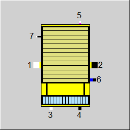 |
Display Option 1 |
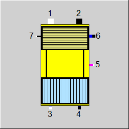 |
Display Option 2 |
Click here >> Component 152 Demo << to load an example.