
EBSILON®Professional Online Documentation


|
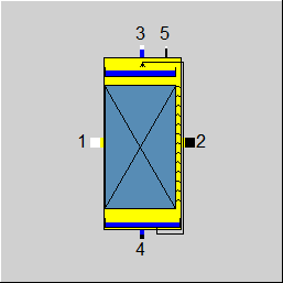
Line connections |
|
|
|
1 |
Air/gas inlet |
|
|
2 |
Air/gas outlet |
|
|
3 |
Water inlet |
|
|
4 |
Water outlet |
|
|
5 |
Logic inlet for NTU (M5) |
|
General User Input Values Characteristic Lines Physics Used References Example
Component 151 Evaporative Cooler can be used to model a device which reduces the temperature of an air or gas stream by means of evaporating liquid water. The amount of heat that can be removed from the air/gas stream equals the heat of evaporation consumed by the phase change of the water. Since this process is controlled by the rate of mass transfer from the liquid to the gaseous phase, there are two key factors to the effectiveness of the cooler: the mass transfer coefficient beta (primarily driven by flow turbulence), and the surface area of the liquid (which can be maximized by appropriate shaping of the metal sheets/packing through which the water flows in cross-low relative to the air/gas stream). If - as typically applied in industrial applications - the surplus water is recirculated to the water inlet, the wet bulb temperature of the air/gas stream represents the minimum for the outlet temperature, and the maximum temperature change that is achievable through this process is limited by the saturation of the air/gas stream.
|
FMODE |
Flag to set the calculation mode Design / Off-design =0: Global |
|
FFU |
Switch ON/OFF =0: OFF (air/gas: outlet = inlet; =1: ON |
|
FDES |
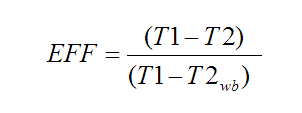
Flag to set the design mode =1: Use EFF (with effectiveness EFF = (T1 - T2)/(T1 - Twet bulb)) =2: Use RHUM (specify exit relative humidity) =3: Desired outlet temperature (T2) =4: Outlet temperature set externally |
|
EFF |
Desired effectiveness (T1 - T2)/(T1 - Twet bulb) |
|
RHUM |
Desired exit relative humidity |
|
T2 |
Desired air/gas outlet temperature |
|
COC |
Cycles of concentration (= ratio of concentration of salt/minerals in recirculated water to concentration in make-up water) |
|
NTU |
Number of transfer units (NTU = beta*A/M1_dry) (RESERVED for later editions, not used) |
|
HLR |
Height to length ratio of channel/packing (uniform distribution of water along width) (RESERVED for later editions, not used) |
|
DP12 |
Pressure drop between air/gas inlet and outlet |
|
FEFFOD |
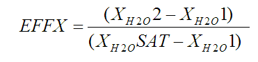
Flag for the off-design effectiveness calculation mode, where EFF = (T1 - T2)/(T1 - Twet bulb), and EFFX = (delta xH2O actual/delta xH2O max) with xH2O max humidity ratio at saturation =0: Constant EFF = EFFN (effectiveness as designed) =1: EFF = CEFF*EFFN (use characteristic line CEFF(VM1/VM1N) for effectiveness correction factor) =2: EFFX = 1 - exp(-BA/M1_dry); BA = CFBA*BAN*(VM1/VM1N)^BAEXP =3: EFFX = 1 - exp(-BA/M1_dry); BA = CBA*BAN (use characteristic line CBA(VM1/VM1N) for beta*A correction factor) |
|
BAEXP |
Off-design exponent for beta*A as a function of (VM1/VM1N) |
|
FDP12OD |
Flag for the off-design pressure drop calculation Like in Parent Profile (Sub profile option only) =0: Constant DP12 = DP12N =1: Depending on volume flow and density (~rho*VM^2) |
|
EFFN |
Nominal effectiveness (T1 - T2)/(T1 - Twet bulb) |
|
VM1N |
Nominal volumetric inlet flow |
|
V1N |
Nominal specific volume at air/gas inlet |
|
DP12N |
Nominal air/gas side pressure drop |
|
BAN |
Nominal beta*A (mass transfer coefficient * surface area) |
|
NTUN |
Nominal number of transfer units (NTU) (not used) |
The parameters marked in blue are reference quantities for the off-design mode. The actual off-design values refer to these quantities in the equations used.
Generally, all inputs that are visible are required. But, often default values are provided.
For more information on colour of the input fields and their descriptions see Edit Component\Specification values
For more information on design vs. off-design and nominal values see General\Accept Nominal values
|
Characteristic line 1: CEFF: Cooler effectiveness correction = f (VM1/VM1N) |
|
1 Volumetric flow ratio 1st point |
|
Characteristic line 2: CFBA: beta*A*(VM1/VM1N)^BAEXP correction = f (VM1/VM1N) |
|
X-Axis 1 Volumetric flow ratio 1st point |
|
Characteristic line 3: CBA: beta*A correction = f (VM1/VM1N) |
|
X-Axis 1 Volumetric flow ratio 1st point |
Energy Balance Model
The mass and energy balance of the evaporative cooler is solved taking account of the evaporation of the water stream that is recirculated in cross-flow to the air/gas stream. Since the recirculated stream of water is significantly larger than the make-up water that compensates for the blow-down and the amount of water that evaporates, it can be assumed that the recirculating water is at the phase equilibrium temperature (= wet bulb temperature). This temperature thus constitutes the minimum exit temperature that is achievable for the air/gas stream flowing through the device, and the cooling effectiveness can be quantified as the ratio of the actual temperature change of the air/gas stream to its maximum temperature change.
From the mass and energy balance, the respective humidity ratios for the actual exit conditions and the ideal state of saturation at the air/gas exit can be determined, and the mass transfer effectiveness EFFX can be calculated as follows:
Design Calculations
|
Mass Balance Equations: |
||
|
|
M1 + M3 = M2 + M4 |
|
|
|
M2 = f(EFFX) = f(EFF) depending on method FDES in design and FEFFOD in off-design, respectively |
|
|
|
M4 = (M2 - M1)/(COC -1) ; COC= ratio of concentration of salt/minerals in recirculated water to concentration in make-up water; COC > 1 |
|
In design mode, the air/gas exit temperature T2 can be defined through various design methods FDES:
Effectiveness EFF
Exit relative humidity RHUM
Exit temperature T2
T2 set externally
In all of these cases, the balances for mass and energy can be closed with the respective input values, and the mass transfer effectiveness EFFX can be determined from the inlet, exit, and saturation conditions. Since the evaporation process can also be described by the laws of mass transfer with beta being the mass transfer coefficient accounting for the flow conditions of the process and A being the surface area available for the phase change, the mass transfer effectiveness can also be expressed with the following equation.
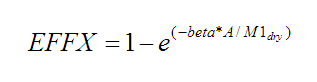
From this equation, the product beta*A can be derived as the nominal value BAN expressing the design characteristic of the evaporative cooler.
Off-Design Calculations
As the flow conditions on the water side do not change, the performance characteristics of the evaporative cooler are primarily affected by the flow conditions on the air/gas side of the equipment which can be expressed as the ratio of volumetric inlet flow at current conditions to the volumetric inlet flow at the design point (VM1/VM1N). The parameter FEFFOD offers several options to adjust the off-design performance characteristics of the evaporative cooler:
0: Constant EFF = EFFN
The cooling effectiveness as designed will be used under all operating conditions.
1: EFF = CEFF*EFFN
The cooling effectiveness will be adjusted by an effectiveness correction factor defined in characteristic line CEFF(VM1/VM1N).
2: EFFX = 1 - exp(-BA/M1_dry); BA = CFBA*BAN*(VM1/VM1N)^BAEXP
The beta*A value of the design case will be adjusted with an exponential function of (VM1/VM1N) with user defined exponent BAEXP and a correction factor defined in characteristic line CFBA(VM1/VM1N).
3: EFFX = 1 - exp(-BA/M1_dry); BA = CBA*BAN
The beta*A value of the design case will be adjusted with a correction factor defined in characteristic line CBA(VM1/VM1N).
Component Displays
 |
Display Option 1 |
Click here >> Component 151 Demo << to load an example.