
EBSILON®Professional Online Documentation


|
Line connections |
|
|
|
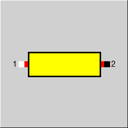
1 |
Inlet |
|
|
2 |
Outlet |
|
General User Input Values Results Displays Example
Together with Components 148 and 149, this component forms a component group that allows to model a common steam header. Only nominally do Pins 1 and 2 represent the inlet and outlet. Any flow direction is possible within the common steam header. With negative mass flows M2 and M1 respectively, however, the inlet is implemented at Pin 2 and the outlet at Pin 1 due to the logic defined in EBSILON. In contrast, positive values for M1 and M2 imply the distribution that is “normal“ for EBSILON (Pin 1 represents the inlet, Pin 2 represents the outlet).
The component can be calculated with the following line types:
- Air
- Flue gas
- Steam
- Water (liquid)
- Crude gas
- Oil (with specifiable composition)
- Coal / solid matter
- Gas (fuel)
- User-defined
- 2-Phase liquid
- 2-Phase gaseous
- Saltwater
By means of Component 150, the pressure drop and the heat loss in the connecting pipe section can be displayed. The specification and calculation respectively of the heat losses and pressure drops can be effected by specifying the nominal values and, in the case of the pressure drop, their scaling in off-design according to Bernoulli’s principle as well as by calculation on the basis of the specified geometry.
|
FMODE
|
Flag for local calculation mode = 0: GLOBAL = 1: Off-design mode = -1: Local Design mode |
|
FDN
|
Flag for defining the thermal losses: = 1: Specification as a heat loss = 2: Thermal loss calculated by geometry |
|
DN |
Thermal loss according FDN (nominal) |
|
FDP |
Flag for switching between phenomenological and geometrical interpretation = 0: phenomenological setting of the pressure loss DP12RN = 1: geometric calculation of the pressure loss of LENGTH, DINNER, ZS and ZETA = -1: No calculation of the pressure drop (P2 externally given) |
|
FDP12RN |
Flag for setting DP12RN as absolute or relative value = 1: DP12RN is used as absolute pressure drop in the design case and as absolute reference pressure drop for off-design calculations: = 2: DP12RN is used in all load cases as the factor by which the current inlet pressure is multiplied to receive the pressure drop in the design case and DP12N=P1*DP12RN. The off-design pressure drop results for DP12=P1*DP12RN*(M1/M1N)^2*V1/V1N . = 3: DP12RN is only used in the design case as the factor by which the current inlet pressure is multiplied to receive the pressure drop. This pressure DP12N=P1N*DP12RN. The off-design pressure drop results for DP12=P1N*DP12RN*(M1/M1N)^2*V1/V1N . = 4: DP12RN is used in all load cases as the factor by which the current inlet pressure is multiplied to directly receive the pressure drop in the respective DP12=P1*DP12RN In this mode, Bernoulli’s principle is not used. |
|
DP12RN |
Pressure loss (nominal) [absolute or relative to P1, according FDP12RN] |
|
LENGTH |
Pipe length |
|
DINNER |
Pipe inner diameter |
|
KS |
Pipe wall roughness |
|
ZETA |
Additional pressure loss zeta |
|
THPIPE |
Thickness of pipe wall |
|
THISO |
Thickness of insulation, may also be 0 |
|
ALPHI |
Inner heat transfer coefficient (to fluid) |
|
ALPHO |
Outer heat transfer coefficient (to ambient) |
|
LAMISO |
Heat conductivity of insulation |
|
FSTAMB |
Definition of ambient temperature =0: specified value (TAMB) |
|
TAMB |
Ambient temperature |
|
M1N |
Mass flow (nominal) |
|
V1N |
Specific volume at inlet (nominal) |
|
P1N |
Inlet pressure (nominal) |
The parameters marked in blue are reference quantities for the off-design mode. The actual off-design values refer to these quantities in the equations used .
Generally, all inputs that are visible are required. But, often default values are provided.
For more information on colour of the input fields and their descriptions see Edit Component\Specification values
For more information on design vs. off-design and nominal values see General\Accept Nominal values
|
DP |
Pressure loss (total) |
|
DPB |
Basic pressure loss |
|
DPZETA |
Additional pressure loss from ZETA |
|
ACALC |
Calculated cross section |
|
WCALC |
Calculated flow velocity |
|
DQ |
Heat loss |
 |
Display option 1 |
Click here >> Component 150 Demo << to load an example.