
EBSILON®Professional Online Documentation


|
Line connections |
|
|
|
1 |
Shaft inlet |
|
|
2 |
Shaft outlet |
|
General User Input Values Physics Used Displays Example
This component allows to model a gearbox or a bearing. Here both the rotational speeds and the energy losses are considered. It can only be used with the line type “Mechanical shaft“.
The gearbox is located between the two shafts and serves to change the speed of rotation.
Here the rotational speed at the outlet can optionally be specified directly as specification value N2 (FSPEC=1), or it can be determined by means of a specified rotational speed ratio N1N2 (FSPEC=2).
For the bearing, the rotational speed remains constant (FSPEC=3).
Five variants are available for representing the gear losses and bearing losses respectively:
|
FMODE |
Flag for calculation mode design/off-design = 0: GLOBAL |
|
FSPEC |
Flag for specification of speeds =1: Gear ratio N1N2 specified |
|
N1N2 |
Gear ratio |
|
N2 |
Output speed |
|
FSPECQ |
Specification of power transmission =1: Use Renk / Tacke formula |
|
ETAN |
Transmission efficiency |
|
QLOSSN |
Transmission loss (nominal) |
|
MU |
Friction coefficient |
|
EQLOSS |
Power loss function |
|
Q1N |
Drive power (nominal) |
Generally, all inputs that are visible are required. But, often default values are provided.
For more information on colour of the input fields and their descriptions see Edit Component\Specification values
For more information on design vs. off-design and nominal values see General\Accept Nominal values
|
Characteristic line1
|
| QLOSS/Q1N = f (Q1 / Q1N) or QLOSS= Q1N* f (Q1/Q1N) X-Axis: Q1/Q1N Y-Axis: QLOSS/Q1N |
|
Characteristic line2
|
| ETA/ETAN = f (Q1/Q1N) or ETA= ETAN * f (Q1/Q1N) X-Axis: Q1/Q1N Y-Axis: ETA/ETAN |
Please note: EBSILON-internally, the rotational speed of a mechanical shaft is mapped onto the mass flow. Therefore the “mass flows” M1 and M2 appear in the equations.
The variables for the pressure (P1 and P2) are not used by the component, but they have to be defined for the equation system. Therefore a pressure equation is
generated as well.
|
All load cases |
||
|
|
if FSPEC=
1: N1N2 * M2 – M1 = 0 (1) 2: M2 = N2 (1) 3: M2 – M1 = 0 (1) P2 – P1 = 0 (2) |
|
|
Design load |
||
|
|
if FSPECQ= 1: if N2<3000
MVGK = 0.7333* MVGMAX 2: ETA = 1 3: ETA = ETAN 4: ETA = 1 5: ETA = 1 H2 – ETA * H1 = -QLOSS (3) |
|
|
Part load cases |
||
|
|
if FSPECQ= 1: if N2<3000
MVGK = 0.7333* MVGMAX 2: ETA = 1 3: ETA = CETA(H1/Q1N) * ETAN 4: ETA = 1 5: ETA = 1 H2 – ETA * H1 = -QLOSS (3) |
|
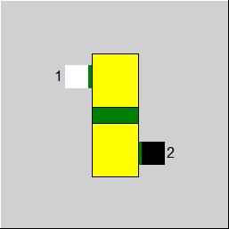 |
Display Option 1 |
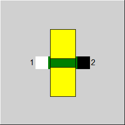 |
Display Option 2 |
Click here >> Component 146 Demo << to load an example.
