
EBSILON®Professional Online Documentation


|
Line connections |
|
|
|
1 |
Feed water inlet |
|
|
2 |
HP live steam outlet |
|
|
3 |
First reheat inlet |
|
|
4 |
First reheat outlet |
|
|
5 |
Thermal boiler duty (as H), (e.g. provided by component 21) |
|
|
6 |
High pressure spray (without throttling) |
|
|
7 |
First reheat spray (without throttling) |
|
|
8 |
Drain / Blow down |
|
|
9 |
Second reheat inlet |
|
|
10 |
Second reheat outlet |
|
|
11 |
Second reheat spray (without throttling) |
|
General User Input Values Characteristic Lines Physics Used Displays Example
This component is an expansion of Component 5 (“Steam generator“) by an additional leg for a second reheat.
Like Component 5, also Component 139 represents an easy way to model a steam generator with specifiable steam parameters without the need to display the individual heating surfaces in detail. It only contains the water/steam side of the boiler. As, however, the required heat demand is determined and output on Logic Pin 5 in an overall balancing of all incoming and exiting energy flows, it can be used as set point value of a controller (Component 12) for modeling a combustion with Component 21. For this purpose, also Component 139 features a view (Form 2) to place the component on a Component 21 (with Form 2, 4, or 5) and optically represent the boiler as an entity.
The expansion for Component 5 consists in an inlet (Pin 9) and an outlet (Pin 10) for the fluid to be heated in the second reheat (by default: steam) as well as an inlet (Pin 11) for a possible injection. The steam outlet temperatures for all legs can optionally be set internally in the component as specification value T2, T4, and T10 respectively or they can be specified from outside. In the case of internal specification, the temperature is assumed to be constant in all load cases.
The inlet temperatures for the feed water and the steam for the two reheat legs are to result from the model from outside.
In the design case, the pressure on the high pressure leg can be set internally with the specification value P2N. The load dependence of the live steam pressure is then defined with the characteristic line CP2. The outlet pressures of the two reheat legs are to result from the model from outside.
In the design case, the pressure drops of the individual legs are set in the specification values DP12N, DP34N, and DP910N. In off-design, a characteristic line CDP12 is available for the high pressure leg. Usually (i.e. FVOL=1) the two reheat legs are scaled according to Bernoulli’s law:
DP34 =(M3/M3N)² * (V3/V3N) * DP34N and
DP910 =(M9/M9N)² * (V9/V9N) * DP910N
Here the flag FVOL allows to use the simplified formulae
DP34 =(M3/M3N)² * DP34N and
DP910 =(M9/M9N)² *DP910N
For using incompressible fluids with FVOL=0 or in order not to scale the pressure drop at all (FVOL=2):
DP34 = DP34N
DP910 = DP910N
The mass flows for all legs have to be specified from outside.
The mass flows of the three injections, however, can be specified in the component relative to the feed water mass flow.
For the high pressure leg, this is effected in the specification value M6M1. This value applies to all load cases.
For the injections into the reheat legs, the mass flows can be defined load-dependent via the characteristic lines CM7M1 and CM11M1. Here it has to be considered that for both characteristic lines the “load” refers to the feed water mass flow (M1/M1N) and not to the mass flow of the respective reheat. Also the result refers to the feed water mass flow in the case of both characteristic lines. This is because it is the respective injection mass flow, related to the feed water mass flow. In contrast to many other characteristic lines, these characteristic lines do not have the value 1 at the position M1/M1N=1, but the ratio of the injection mass flow to the feed water mass flow in the design point. Therefore these characteristic lines are also used in the design calculation.
Like in Component 5, also in Component 139 there is an outlet for a blow-down. Its mass flow can optionally be specified via the internal specification value M8M1 or from outside. The pressure of the blow-down is defined by the specification value DPECON. Here DPECON is the pressure drop between the feed water inlet and the blow-down. The enthalpy of the liquid boiling at this pressure is assumed as the enthalpy of the blow-down.
In Component 139, a separate flag has been implemented for each optionally specifiable quantity. Here “0“ stands for the specification in the component and “1“ for the specification from outside. The use of combined flags like in Component 5 (e.g. “T2, P4 given from outside, T4 internally“) would have been too confusing here.
CAUTION:
While modeling injections and drains care must be taken to use these with the remaining circulation, as otherwise a violation of the mass balance can occur.
|
FMODE |
Flag for calculation mode =0: GLOBAL =1: Local off-design = -1: Local design |
|
FP2 |
Live steam pressure specification Like in Parent Profile (Sub profile option only) Expression =0: P2 determined by P2N and CP2 |
|
P2N |
Live steam pressure (nominal) |
|
DP12N |
HP-pressure loss (between ports 1 and 2) (nominal) |
|
FT2 |
Live steam temperature specification Like in Parent Profile (Sub profile option only) Expression =0: T2 given by specification value T2 |
|
T2 |
Live steam temperature |
|
FM6 |
High pressure spray specification Like in Parent Profile (Sub profile option only) Expression =0: M6 calculated from specification value M6M1 |
|
M6M1 |
HP-injection mass flow, (relative to feed water M1) |
|
DP34N |
First reheat pressure drop (nominal) |
|
FT4 |
First reheat hot temperature specification Like in Parent Profile (Sub profile option only) Expression =0: T4 given by specification value T4 |
|
T4 |
First reheat hot temperature |
|
FM7 |
First reheat spray specification Like in Parent Profile (Sub profile option only) Expression =0: M7 calculated from characteristic CM7M1 |
|
DP910N |
Second reheat pressure drop (between ports 9 and 10) (nominal)
|
|
FT10 |
Second reheat hot temperature specification Like in Parent Profile (Sub profile option only) Expression =0: T10 given by specification value T10 |
|
T10 |
Second reheat hot temperature |
|
FM11 |
Second reheat spray specification Like in Parent Profile (Sub profile option only) Expression =0: M11 calculated from specification value CM11M1 |
|
FM8 |
Drainy specification Like in Parent Profile (Sub profile option only) Expression =0: M8 calculated from specification value M8M1 |
|
M8M1 |
Draining mass flow (relative to nominal feed water flow) |
|
DPECON |
Economizer pressure drop (for determination of drain pressure), (nominal)
|
|
FVOL |
Part-load pressure drop (reheat only) Like in Parent Profile (Sub profile option only) Expression =0: only depending on mass flow =1: depending on mass and volume flow =2: Constant (equal nominal value) |
|
M1N |
Feed water mass flow (nominal) |
|
M3N |
First reheat mass flow (nominal) |
|
V3N |
Specific volume of first reheat (cold side) (nominal) |
|
M9N |
Second reheat mass flow (nominal) |
|
V9N |
Specific volume of second reheat (cold side) (nominal) |
The identification values marked in blue are reference values for off-design mode. These values are referred to for the actual off-design values used in the equations respectively. If these identification values are stream data, then these values are often taken from attached pipes or calculated values.
Generally, all inputs that are visible are required. But, often default values are provided.
For more information on colour of the input fields and their descriptions see Edit Component\Specification values
For more information on design vs. off-design and nominal values see General\Accept Nominal values
Characteristic lines CPD12, CPD34, CPD910: The default characteristic lines have a constant value of 1.0. A calculation based on physical laws should be more accurate than a default characteristic curve in most cases. In particular, a dependence on the volume flow cannot be taken into account at all in the characteristic line. And to regard steam as an incompressible fluid is probably a rather rough approximation.
|
Characteristic 1 (CP2) : HP-sliding pressure-characteristic P2/P2N = f(M1/M1N) |
|
X-Axis 1 M1/M1N 1st point |
|
Characteristic 2 (CDP12) : HP-pressure loss DP12/DP12N = f(M1/M1N) |
|
X-Axis 1 M1/M1N 1st point
|
|
Characteristic 3 (CDP34) : RH-pressure loss DP34/DP34N = f(M3/M3N) |
|
X-Axis 1 M3/M3N 1st point
|
|
Characteristic 4(CDP910): RH-pressure loss , 2. RH DP910/DP910N = f(M9/M9N) |
|
X-Axis 1 M9/M9N 1st point
|
|
Characteristic 5 (CM7M1) : 1st RH spray water M7/M1 = f(M1/M1N) |
|
X-Axis 1 M1/M1N 1st point |
|
Characteristic 6 (CM11M1) : 2nd RH spray water M11/M1 = f(M1/M1N) |
|
X-Axis 1 M1/M1N 1st point |
|
Design case |
||
|
M2 - M1 - M6 + M8 = 0 (1) if FM6=0: M6 – M6M1 * M1 = 0 (2) if FP2=0: P2 = P2N (3) P2 – P1 =DP12N (4) if FT2=0: H2 = f(P2,T2) (5) M4 – M3 – M7 = 0 (6) if FM7=0: M7 – CM7M1(1)* M1 = 0 (7) P3 – P4 = DP34N (8) if FT4=0: H4 = f(P4,T4) (9) M10 – M9 – M11 = 0 (10) if FM11=0: M11 – CM11M1(1)* M1 = 0 (11) P9 – P10 = DP910N (12) if FT10=0: H10 = f(P10,T10) (13) if FM8=0: M8 – M8M1 * M1 = 0 (14) P8 – P1 = DPECON (15) H8 = H’(P8) (16) H5+M1*H1+M3*H3+M9*H9+M6*H6+M7*H7+M11*H11-M2*H2-M4*H4-M10*H10-M8*H8=0 (17) |
||
|
Off-design |
||
|
M2 - M1 - M6 + M8 = 0 (1) if FM6=0: M6 – M6M1 * M1 = 0 (2) if FP2=0: P2 = CP2(M1/M1N) * P2N (3) P2 – P1 = CDP12(M1/M1N) * DP12N (4) if FT2=0: H2 = f(P2,T2) (5) M4 – M3 – M7 = 0 (6) if FM7=0: M7 – CM7M1(M1/M1N)* M1 = 0 (7) if FVOL = 0: DP34 =(M3/M3N)² * DP34N 1: DP34 = (M3/M3N)² * (V3/V3N)*DP34N 2: DP34 = DP34N P3 – P4 = DP34 (8) if FT4=0: H4 = f(P4,T4) (9) M10 – M9 – M11 = 0 (10) if FM11=0: M11 – CM11M1(M1/M1N)* M1 = 0 (11) if FVOL = 0: DP910 =(M9/M9N)² * DP910N 1: DP910 = (M9/M9N)² * (V9/V9N)* DP910N 2: DP910 = DP910N P9 – P10 = DP910 (12) if FT10=0: H10 = f(P10,T10) (13) if FM8=0: M8 = M8M1 * M1N (14) P8 – P1 = DPECON (15) H8 = H’(P8) (16) H5+M1*H1+M3*H3+M9*H9+M6*H6+M7*H7+M11*H11-M2*H2-M4*H4-M10*H10-M8*H8=0 (17) |
||
|
Relative mass flow feed water |
M1/M1N |
|
Relative mass flow reheat
|
M3/M3N |
|
Relative live steam pressure |
P2/P2N |
|
Relative live steam pressure drop
|
DP12/DP12N |
|
Relative reheat steam pressure drop |
DP34/DP34N |
|
2. RH :Relative mass flow reheat
|
M9/M9N |
|
2. RH: Relative reheat steam pressure drop |
DP910/DP910N |
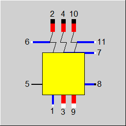 |
Form 1 |
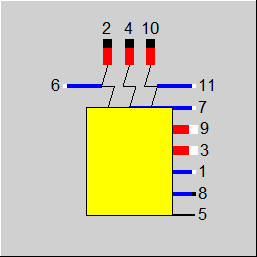 |
Form 2 |
Click here >> Component 139 Demo << to load an example.