

|
Line Connection |
|
|
|
1 |
Power Outlet |
|
General User Input Values Results Specification Matrices Physics Used Displays Example
Component 137 (PV System) is used to model electric power generation from a single or an array of photovoltaic modules that can be connected in series or in parallel, or both. It only works in conjunction with a Sun (component 117) that has to be referred to in the parameter ISUN, and which provides sun position and irradiance. Various types of PV cells and the following tracking options to adjust the incidence angle on the panel can be selected:
![]()
Data from various manufacturers have been stored in the default value database for this component.
| ISUN | Index for solar parameters (= selector which component 117 shall be used in the calculation) |
| NMODSER | Number of PV modules in series Note: This number multiplied by the open circuit voltage of the module shall be less than the maximum voltage of the inverter. |
| NMODPAR | Number of PV modules in parallel Note: This number multiplied by the number of modules in series and by the open circuit current of the module shall be less than the maximum current of the inverter. |
| FCELLTYPE |
Method to specify PV cell type
|
| FIANGLE |
Method to specify PV cell incidence angle settings
|
| AZIM | Cell azimuth (0° = north, projection of the cell normal vector to the horizontal plane) |
| TILT | Cell slope (0° = horizontal, 90° = vertical) |
| AZIRANGE | Azimuth tracking range (effective angle will be in the range 180° ± AZIRANGE/2) |
| MINTILT | Minimum tilt angle |
| MAXTILT | Maximum tilt angle |
| FHGR |
Method to specify ground reflectance
|
| HGR | Ground reflectance |
| FCOT |
Method to specify cell operating temperature calculation
|
| COT | Cell operating temperature |
| FNOCT |
Method to select correction type
|
| NOCT | Nominal operating cell temperature (800W, 20°C, 1 m/s) |
| FCMOUNT |
Method to specify module mount type
|
| FSHADING |
Method of shading radiation losses - the output is reduced by these relative losses =0: No shading losses |
| SHADINGLOSS | Shading radiation losses fraction |
| ESHADINGLOSS | Expression for shading radiation losses |
| TYPENAME | Panel Model Name |
| IRRR | Reference Condition Irradiance |
| TR | Reference Condition Cell Temperature |
| FPARAM |
Model parameter flag =0: Manufacturer data sheet |
| VT |
Ideality factor, thermal voltage |
| IL |
Light current |
| I0 |
Diode reverse saturation current |
| RS |
Series Resistance |
| RP |
Parallel Resistance |
| NS |
Number of single cells in series |
| ISCR | Reference Condition Short Circuit Current |
| VOCR | Reference Condition Open Circuit Voltage |
| IMPPR | Reference Condition Current at Maximum Power Point |
| VMPPR | Reference Condition Voltage at Maximum Power Point |
| TCISCR | Reference Condition Temperature Coefficient for ISC |
| TCVOCR | Reference Condition Temperature Coefficient for VOC |
| AREA | Area per module (for efficiency calculation only) |
| CF | Cleanliness factor (= overall performance correction factor); value of 1.0 represents new and clean |
| Q | Total electrical output at maximum power point (MPP) = QMPP * NCELLSER * NCELLPAR |
| QMPP | Electrical output per module (MPP) |
| IMPP | Current per module (MPP) |
| VMPP | Voltage per module (MPP) |
| EFFMPP | Efficiency at maximum power point (MPP) |
| BEAMHI | Beam horizontal irradiance |
| DIFFHI | Diffuse horizontal irradiance |
| GLOBHI | Global horizontal irradiance |
| GLOBTI | Global tilted irradiance |
| RAZIM | Used Azimuth angle |
| RSUNAZIM | Sun azimuth angle |
| RSUNELEV | Sun elevation angle |
| RTILT | Used tilt angle |
| RINC | Used incidence angle |
| RCOT | Used operating temperature |
| RSHADINGLOSS | Shading radiation losses fraction |
| RHORIZON | Calculated Horizon Angle |
|
Characteristic 1 |
| Loss fraction = f (sun angle over the horizon) X-axis : Sun angle over horizon Y-axis : Loss fraction |
MXSHADINGLOSS: Shading radiation losses: Sun elevation angle as a function of radiation loss fraction and sun azimuth angle
Solar position and normal beam (direct) irradiance are determined by the component 117 (Sun) that the PV module is referred to through the index defined in the input value ISUN. The amount of diffuse irradiance is calculated according to the model of Orgill and Hollands (1977), and ground irradiance (i.e. through reflection from the surroundings) is taken into account using ground reflectance (Albedo) values according to TÜV (1984) for different materials in the method FHGR. The total absorbed radiance on the cell surface results from the contribution of beam radiance (Gb adjusted for tilted surface by ratio factor Rbeam), of diffuse radiance (Gd) , and ground radiance (G * rg) each multiplied by its respective view factor (b = SLOPE).
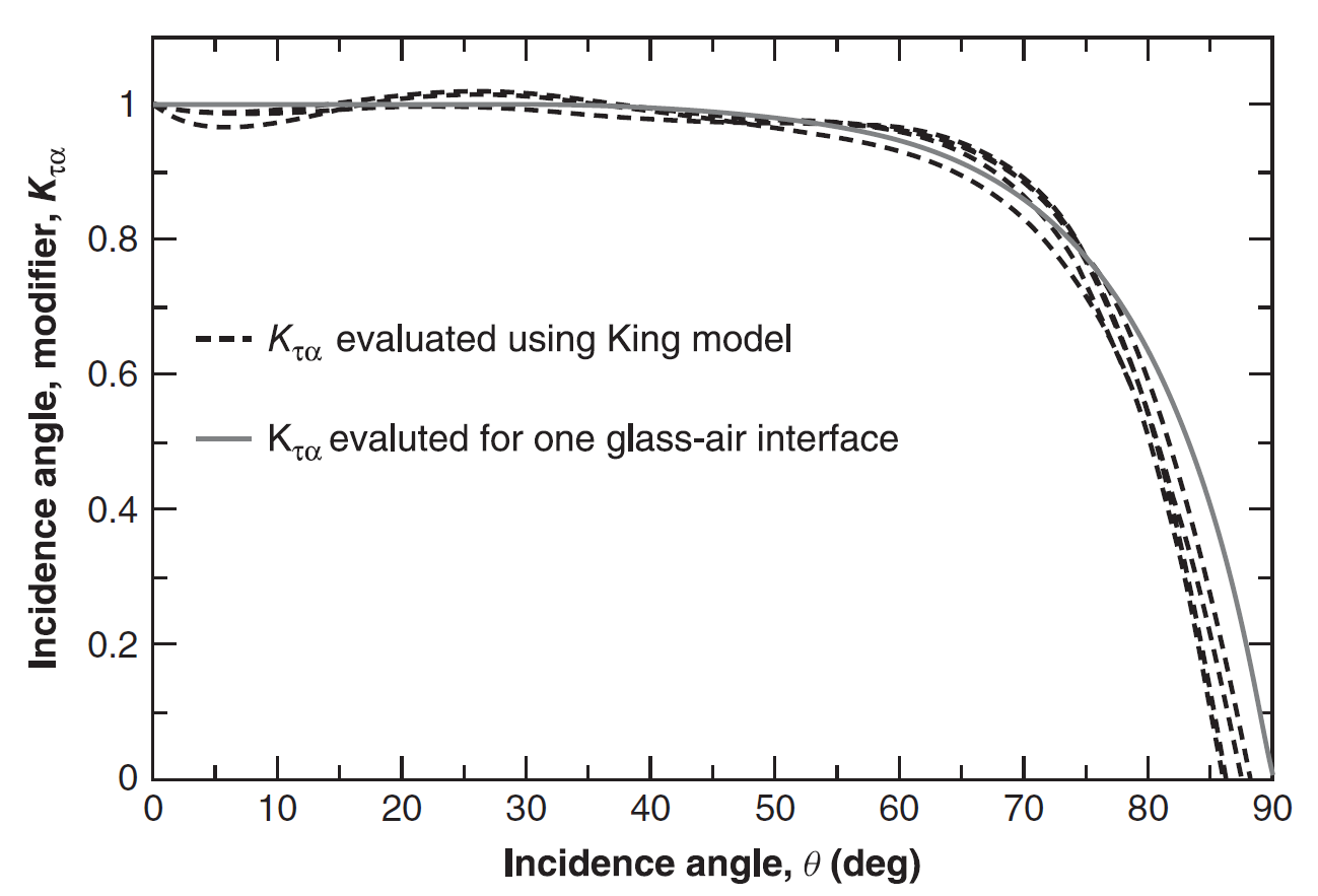
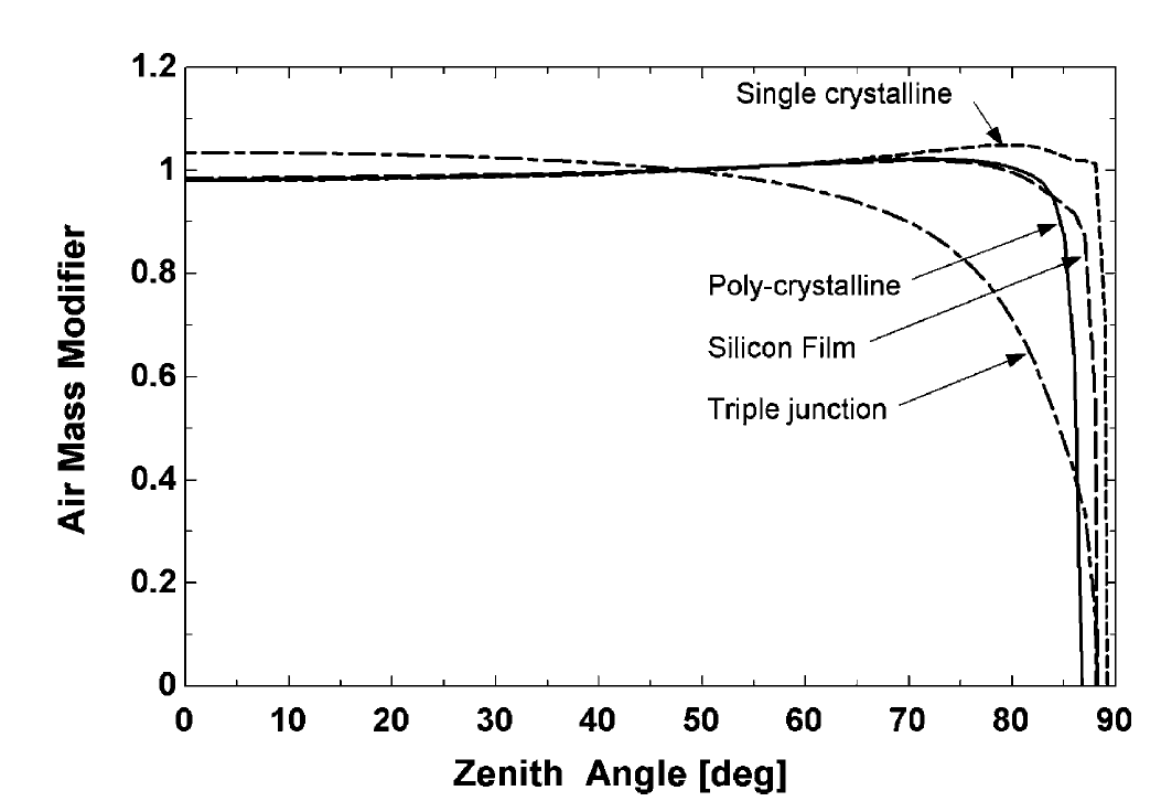
Sref in the above equation is the absorbed radiance at cell standard conditions (NIST SRC: 1000 W/m2, 25°C, RCINC = 0°, consequently Mref = 1). The effect of the incident angle (i.e. the angle between the direction of the beam and the normal to the panel) is represented through the incident angle modifier Kta that constitutes the ratio of transmittance at an incidence angle RCINC to transmittance at RCINC = 0°. For RCINC larger than 65° the effects of reflection from the cell surface typically become significant and absorption decreases sharply, see the graph below.
Current-voltage (I -V) characteristics of a typical PV module are shown in the figure to the left below. The intersection with the current axis (where V = 0) is the short-circuit current Isc, and the intersection with the voltage axis (where I = 0) is the open-circuit voltage Voc. For this module the current decreases slowly to about 15V and then decreases rapidly to the open-circuit conditions at about 21.4 V. For comparison, a single 1-cm2 silicon cell at a solar radiation level of 1000 W/m2 has an open-circuit voltage of about 0.6V and a short-circuit current of about 20 to 30 mA.
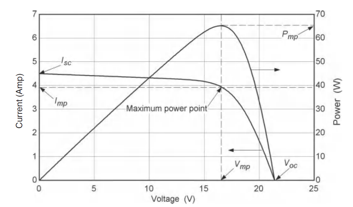
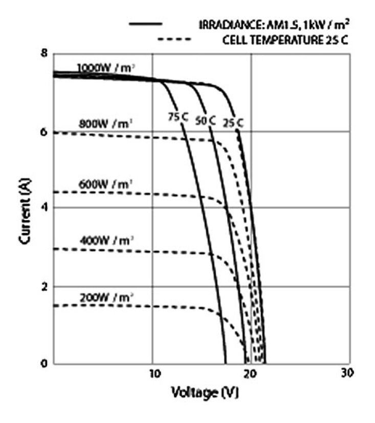
The maximum power that can be obtained corresponds to the rectangle of maximum area under the I–V curve. At the maximum power point the power is Pmp, the current is Imp, and the voltage is Vmp. Today industrial inverters provide good MPP-Trackers up to a tracking efficiency of 99.99%. This justifies the assumption that the MPP-Point of a PV-Module can always be found, if it lies within the tracking range of the inverter. The right-hand figure above shows how irradiance and cell temperature affect the I-V curve: current is primarily affected by irradiance, and voltage by cell temperature. In order to account for these performance characteristics De Soto et al. (2006) developed a refined Five-Parameter-Model describing the I-V curve in analogy to a circuit consisting of a series resistance (Rs) and a diode in parallel with a shunt resistance (Rsh), as shown in the figure below.
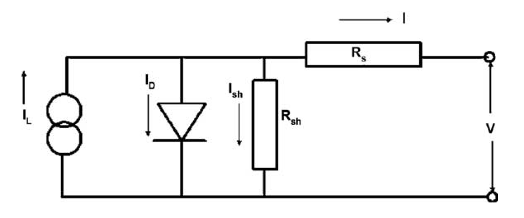

Using results from measurements at reference conditions (for most of the PV manufacturers reference condition irradiance IRRR is 1000 W/m2 and reference condition cell temperature TR is 25°C) the following parameters to characterize the I-V curve for a specific PV cell are derived (with the respective variable name in EBSILON®Professional in parentheses): short circuit current at V = 0 (ISCR), open circuit voltage at I = 0 (VOCR), current at maximum power point (IMPPR), voltage at maximum power point (VMMPR), temperature coefficient for ISC (TCISCR), and temperature coefficient for VOC (TCVOCR).
Using this model and the total absorbed radiance resulting from the operating conditions, the light current IL and consequently the maximum power point at current conditions (IMPP, VMPP) are derived.

In this equation IL,ref = IMPPR * VMPPR, and cell operating temperature Tc (COT) is calculated as per the setting in the method FCOT with the following options: user input COT, according to Skoplaki (2008), or linear with irradiance. The method of Skopalki (2008) estimates the cell operating temperature by correlation with ambient temperature and wind speed (both read from the component 117 specified in ISUN) and a factor for the mounting type (specified in method FMOUNT).The linear model correlates cell operating temperature with ambient temperature, the ratio of current irradiance (GLOBTI) to reference condition irradiance (IRRR), and the factor for the mounting type.
Since the reference conditions for the Five-Parameter-Model (i.e. room and cell temperature controlled to exactly 25°C) oftentimes differ significantly from the ambient conditions in practical applications, many vendors also specify the so-called Nominal Operating Cell Temperature (NOCT) at normal conditions of 800 W/m2, 20°C, 1 m/s wind speed, and free standing mounting. Since both, the method of Skoplaki and the linear correlation with irradiance do not contain a reference to this NOCT, the results of correlations oftentimes do not match the vendor NOCT. With the method FNOCT set to "Adjust to NOCT: 1", the slope of the respective equation will be adjusted to exactly match the vendor data at normal conditions.
In order to account for fouling and/or performance degradation of the module, the absorbed irradiance is multiplied with a cleanliness factor (CF). As this correction affects the optical characteristics, the effect of the cleanliness factor on the overall power output is not linear. Cell temperature calculations are not affected.
The electric current at port 1 of the PV module is direct current, and therefore the values for frequency/rotary speed and power factor of the connecting line will be set to F = 0 and COSP = 1, respectively. In order to be able to supply this current into the electricity grid, it is necessary to convert to alternating current or 3-phase AC by means of an inverter. As shown in the sample model for the PV module, the inverter can be easily modelled in EBSILON with a value transmitter (Component 36). On the exiting electric line the user just has to specify voltage, frequency and power factor with respective measuring points (Component 46), and the efficiency of the inverter can be entered as the multiplier of the value transmitter for the energy flow (signal type enthalpy).
De Soto et al. (2006)
W. De Soto, S.A. Klein, W.A. Beckmann, Improvement and validation of a model for photovoltaic array performance, Solar Energy 80 (2006) 78–88
King et al. (2004)
King, D. L., W. E. Boyson, and J. E. Kratochvil, Photovoltaic Array Performance Model, Sandia National Laboratories Report SAND 2004–3535 (Aug. 2004)
Skoplaki et al. (2008)
Skoplaki, E., Boudouvis, A.G., Palyvos, J.A., A simple correlation for the operating temperature of photovoltaic modules of arbitrary mounting. Solar Energy Materials & Solar Cells, Volume 92, Pages 1393-1402, 2008
Orgil and Hollands(1977)
Orgill, J. F. and K. G. T. Hollands, ‘‘Correlation Equation for Hourly Diffuse Radiation on a Horizontal Surface’’ Solar Energy, 19, 357 (1977)
TÜV (1984)
TÜV-Rheinland: Atlas über die Sonnenstrahlung in Europa. TÜV-Verlag, 1984
General Reading
J.A. Duffie, W.a. Beckman: Solar Engineering of Thermal Processes, Fourth Edition, Wiley-Interscience, New York, 2013
 |
Display Option 1 |
Click here >> Component 137 Demo << to load an example.