
EBSILON®Professional Online Documentation


|
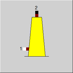
Line connections |
|
|
|
1 |
Inlet |
|
|
2 |
Outlet |
|
General User Input Values Physics Used Displays Example
Component 135 is used to model a power plant stack that induces a draft at its inlet due to the differences in temperature and height between the flue gas and the ambient air. In design mode, the user can select between the calculation of the required stack height as a function of desired draft pressure difference and the calculation of resulting pressure difference as a function of stack height. In off-design, the stack height is fixed and the draft resulting from the current inlet conditions and ambient will be determined. Heat losses from the stack can be defined as temperature difference between stack inlet and stack outlet.
|
FMODE |
Calculation mode (design / off-design)
|
|
HFGINLET |
Flue gas inlet height (elevation of stack inlet above ground); |
|
FDRAFT |
Draft calculation mode
|
|
DRAFTDP |
Desired draft pressure difference |
|
HSTACK |
Desired stack height |
|
FPAMB |
Ambient pressure source
|
|
PAMB |
Ambient pressure (at stack inlet level) |
|
FSTAMB |
Definition of ambient temperature
|
|
TAMB |
Ambient temperature |
|
ISUN |
Index for solar parameters (= selector which component 117 shall be used in the calculation) |
|
DTSTACK |
Stack temperature drop |
|
HSTACKN |
Required stack height (nominal) |
The parameters marked in blue are reference quantities for the off-design mode. The actual off-design values refer to these quantities in the equations used.
Generally, all inputs that are visible are required. But, often default values are provided.
For more information on colour of the input fields and their descriptions see Edit Component\Specification values
For more information on design vs. off-design and nominal values see General\Accept Nominal values
| RTAMB | Ambient temperature used in calculations |
| RPAMB | Ambient pressure used in calculations |
| RDPDRAFT | Calculated draft pressure difference |
| RHSTACK | Required stack height |
| HTOTAL | Total stack height (= RHSTACK + HFGINLET) |
| VMSTACK | Stack volume flow |
The stack uses the barometric height formula applied to both, the flue gas inside the stack and the surrounding ambient air, for the calculation of the resulting draft (i.e. the pressure difference between the ambient pressure and the flue gas pressure at the stack inlet).

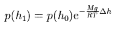
In this formula, Dh denotes the geodetic height difference between the two locations h0 (bottom) and h1 (top), and T(h0) is the temperature at the level h0. While the composition of the ambient air is assumed to be that of the standard atmosphere (resulting in a temperature coefficient a = 0.0065 K/m and ratio of molecular weight to universal gas constant Mg/Ra = 5.255), the respective value for Mg/Ra is derived from the composition of the flue gas, and the temperature coefficient is calculated from the user input for stack temperature drop DTSTACK and the stack height. In design mode, where the user may select the method FDRAFT = 1 to calculate the stack height as a function of desired draft, the stack height is determined through numerical iteration.
If no difference in flow gas temperature between stack inlet and outlet is defined (i.e. DTSTACK = 0), then the barometric height formula for the flue gas transforms to the following relation:
Velocity effects at the stack outlet are assumed to be negligible, as well as the influence of the geodetic height difference between the bottom of the stack and the flue gas inlet to the stack (HFGINLET).
Since the required height of the stack is calculated as the height difference between flue gas inlet and stack outlet, the total height of the stack (i.e. the height of the stack outlet above ground) is calculated as the sum of the required height and the user input for the flue gas inlet height HFGINLET.
 |
Display Option 1 |
Click here >> Component 135 Demo << to load an example.