
EBSILON®Professional Online Documentation


|
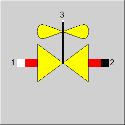
Line connections |
|
|
|
1 |
Inlet |
|
|
2 |
Outlet |
|
|
3 |
Connection for DP, Travel |
|
General User Input Values Results Characteristic Lines Physics Used Displays Example
This component describes the relationship between the pressure drop and the flow rate through a control valve depending on the
a) KV value - the flow coefficient of the valve at rated travel (input value KVS) and
b) KV-Characteristic of the valve as a function of the valve travel (characteristic line 1 CLKV)
All definitions are according to DIN EN 60534 and VDI/VDE 2173.
The component can be used for liquid (incompressible) or gas (compressible) media. However phase transitions or two-phase flows are not covered in the physics used and the corresponding error message appears if such situations occur.
Specifications include
• the values of KVS, the valve travel and either the flow rate or the pressure change, in this case either the not specified flow rate or the pressure drop will be computed (FCALC = 1,2,3), or
• the values of the flow rate and the pressure drop, in this case the value of the flow coefficient KV will be computed (identification mode, FCALC = 4,5).
The following conditions are checked for,
• for incompressible media, a warning appears at partial cavitation condition. To make sure this check to be reliable the user must specify the reasonable values (ideally provided by the valve manufacturer) for the input value XFZN and the characteristic line CLXFZ.
• for all media, the flow rate and the pressure drop are compared to the maximum values at choked flow condition. At choked flow and FLIM=0 the corresponding warning appears. For FLIM=1 and FCALC=2,3 additionally the computed flow rate is limited to the maximum value. To make sure this check to be reliable the user must specify the reasonable values (ideally provided by the valve manufacturer) for XTN and the characteristic line CLXT for gas media and for FLN and the characteristic line CLFL for liquid media.
The flow coefficient KV is defined as
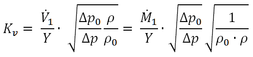
 - volumetric flow rate at valve inlet
 - mass flow rate at valve inlet
 - reference pressure drop (for SI definition 1 bar)
 - reference density (for SI definition 1000 kg/m³)
 - expansion factor, which is equal 1 for incompressible media
For compressible media
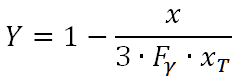
The expansion factor value varies between 2/3 and 1.
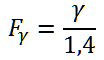
 - the ratio between the specific heat ratio

and 1,4 (which is the value for air)
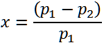
 - the differential pressure ratio (relevant for compressible media)
 - the differential pressure ratio at which choked flow occurs
The the US unit system the flow coefficient CV is defined as the volumetric flow rate of water in USgal/min at pressure drop of 1 psi (Δp0=1 psi) and the temperature of 60 °F (approx. 15,6°C). The values of KV and CV are in the numerical relationship: KV = 0,865 * CV.
The value of KVS denotes the value of KV at rated travel of the valve (valve open 100%).
A characteristic line describes the dependency of the KV value from the valve travel and is used for the off-design / part load mode. Typically, this characteristic line has a linear or an equal percentage shape.
The actual characteristic line KV = f(Hub) can deviate from the theoretical one (linear or equal percentage).
The definition of the flow coefficient KV is documented for one-phase media in the guideline DIN EN 60534 and VDI/VDE 2173 and is related to the water at the temperature between 5°C and 40°C and pressure drop of 1 bar. For multi-phase flows there is a problem of the accurate density definition for the mixture of phases. Different modeling proposals made in the past have not been accepted as a standard yet. Hence the current implementation of the component 133 is limited to one-phase media only.
The control of maximum pressure drop value Δpmax / choked flow occurrence varies depending of the fluid type / fluid phase
For one-component liquid media (e.g. liquid water) DP12 is compared to DPMAX which, in turn, is computed using the value of FL (liquid pressure recovery factor).
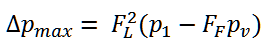
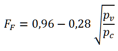
where Pc – critical pressure
and Pv – saturation pressure at temperature T1
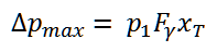
For the mixture of gases (e.g. air) or one-component gaseous media (e.g. water steam) the occurrence of choked flow is controlled comparing the value of X to the value of Fγ*XT
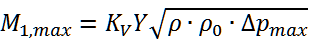
The volumetric flow rate V1MAX and the mass flow rate M1MAX corresponding to DPMAX are computed using the KV value as
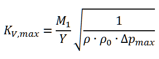
On the other hand the limiting value KVMAX can be computed using the values of DPMAX and M1:
|
FMODE |
Flag for calculation mode =0: GLOBAL |
|
FDEF |
Flag for the definition of the flow coefficient =0: SI, water at 5-40°C, DP=1 bar (KV) =1: US, water at 40-100°F, DP=1psi (CV) |
|
KVS |
KV-value at the rated travel (100%) |
|
FTRAVEL |
Flag for the specification of the actual TRAVEL (for FCALC<4 only) =0: Using TRAVEL value =1: Using H3 value (enthalpy at PIN3) |
|
TRAVEL |
actual travel, for off-design only. This value is used as x value for the char. lines 1-3 only if FTRAVEL=0 and FCALC=1,2,3. If FCALC=4,5 this value is ignored. Instead the result value TRAVELCL is computed using the computed KV-value and the char.line 1 If FTRAVEL=1 this value is ignored. Instead the value of H3 is used for the travel specification |
|
FDP12D |
Flag for the specification of the desired pressure drop =0: Using DP12D value =1: Using P3 value (pressure at PIN3) |
|
DP12D |
desired DP12 (for FCALC = 3 or FCALC=5 only) |
|
FCALC |
Calculation mode =1: TRAVEL and M1 given, DP12 computed =2: TRAVEL and P1 and P2 given, M1 computed =3: TRAVEL and DP12D given, M1 computed =4: M1, P1 and P2 given, KV computed. Identification, Char.line F(TRAVEL) is ignored, TRAVELCL is computed using KV and F(TRAVEL) =5: M1 and DP12D given, KV computed. Identification, Char.line F(TRAVEL) is ignored, TRAVELCL is computed using KV and F(TRAVEL) |
|
FLIM |
Flag for the flow limitation (if choked flow occurs) =0: OFF. The limit values DPMAX, M1MAX, VM1MAX, KVMAX are computed, warning appears at limit violation, but no active limitation of M1 =1: ON. M1 is limited at choked flow condition for FCALC=2 or FCALC=3 only. Attention! reasonable specification values for FLN, XTN are expected for accurate results. |
|
FLN |
Liquid pressure recovery factor nominal. Relevant for liquid media |
|
XFZN |
Difference pressure ratio at transition to cavitating flow XFZ (nominal). Relevant for liquid media and partial cavitation. XFZ=DP12Krit/(P1-P1SAT). DP12Krit is computed using XFZ. If DP12>DP12Krit the partial cavitation occurs |
|
XTN |
Difference pressure ratio at which choked flow occurs (nominal). Relevant for gaseous media |
|
DP12N |
Pressure drop nominal (TRAVEL= 100%) |
|
M1N |
Mass flow nominal |
|
VM1N |
Volume flow at inlet nominal |
|
V1N |
Specific volume at inlet nominal |
The identification values marked in blue are reference values for off-design mode. These values are referred to for the actual off-design values used in the equations respectively. If these identification values are stream data, then these values are often taken from attached pipes or calculated values.
Generally, all inputs that are visible are required. But, often default values are provided.
For more information on colour of the input fields and their descriptions see Edit Component\Specification values
For more information on design vs. off-design and nominal values see General\Accept Nominal values
|
KV |
actual flow coefficient KV-value |
|
DP12 |
actual pressure drop |
|
TRAVELCL |
Actual valve travel according to char. line (can deviate from TRAVEL input value if FCALC>3). This value is computed from the inverse look up of the char.line 1 for FCALC=4,5. |
|
KVREF |
reference value of KV (char.line KV=f(TRAVEL)) |
|
DPREF |
pressure drop reference value (char.line KV=f(TRAVEL) and M1) |
|
M1REF |
mass flow reference value (char.line KV=f(TRAVEL) and DP12) |
|
VM1REF |
volume flow reference value (char.line KV=f(TRAVEL) and DP12) |
|
X |
differential pressure ratio DP12/P1 (relevant for gases) |
|
XF |
differential pressure ratio DP12/(P1-P1SAT) (relevant for liquids) |
|
FL |
liquid pressure recovery factor from char. line 3 |
|
XT |
differential pressure ratio at which choked flow occurs from char. line 2 |
|
XFZ |
differential pressure ratio at transition to cavitation XFZ=DP12Krit/(P1-P1SAT) |
|
DPMAX |
pressure drop at which choked flow occurs |
|
V1MMAX |
volume flow M1 corresponding to DPMAX and KV |
|
M1MAX |
mass flow M1 corresponding to DPMAX and KV |
|
KVMAX |
KV value corresponding to DPMAX and M1 |
|
Characteristic line 1: Flow coefficient KV/KVS = f(TRAVEL) |
|
X-Axis 1 TRAVEL 1. point |
|
Characteristic line 2: Differential pressure ratio for choked flow XT/XTN = f(TRAVEL) |
|
X-Axis 1 TRAVEL 1. point |
|
Characteristic line 3: Liquid pressure recovery factor FL/FLN = f(TRAVEL) |
|
X-Axis 1 TRAVEL 1. point |
|
Characteristic line 4: Differential pressure ratio at transition to cavitating flow XFZ/XFZN = f(KV/KVS) |
|
X-Axis 1 KV/KVS 1. point |
|
If FDEF=0 DP0 = 1 bar If FDEF=1 DP0 = 1 psi = 0,068944 bar RHO0 = 1000 (kg/m³) KVREF from char.line 1 CLKV XT from char.line 2 CLXT FL from char.line 3 CLFL XFZ from char.line 4 CLXFZ X=(P1-P2)/P1 – differential pressure ratio If on PIN1 and PIN2 liquid fluid Y = 1 XF = (P1-P2)/(P1-PSAT(T1)) If on PIN1 and PIN2 steam / gas / gas mixture FY = GAMMA/1,4 Y= 1 – X/(3*FY*XT) DPREF = DP0/(RHO1*RHO0) * (M1/(KVREF*Y)) * (M1/(KVREF*Y)) M1REF = KVREF*Y*SQRT(DP12*RHO0*RHO1/DP0) VM1REF = M1REF/RHO1 If FLIM=1 (limitation activated) If M1REF>M1MAX then M1REF=M1MAX
Mass balance: M1 - M2 = 0 If FCALC=2 or FCALC=3 M1 = M1REF
Pressure balance: If FCALC<>2 and FCALC<>4 If FCALC=1 P1 – P2 = DPREF else P1 – P2 = DP12D
Enthalpy balance: H1 - H2 = 0 (adiabatic process)
Limit values: If compressible (gas, steam): DPMAX = P1*FY*XT If incompressible (liquid): PCRIT – critical pressure FF = 0.96-0.28*SQRT(P1SAT/PCRIT) DPMAX = FL*FL*(P1-FF*P1SAT) M1MAX = KV*Y*SQRT(RHO1*DPMAX*RHO0/DP0) VM1MAX = M1MAX/RHO1 KVMAX = M1/Y*SQRT(DP0/(RHO1*DPMAX*RHO0))
Control of partial cavitation (only for liquids) DP12Krit is computed using XFZ (Char.line 4) and XFZ=DP12Krit/(P1-P1SAT) If DP12>=DP12Krit, warning: partial cavitation! |
|
 |
Display Option 1 |
Click here >> component 133 Demo << to load an example.