
EBSILON®Professional Online Documentation


|
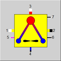
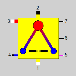
Line connections |
|
|
|
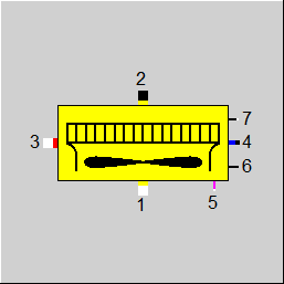
1 |
Air inlet |
|
|
2 |
Air outlet |
|
|
3 |
Hot side inlet (Steam or Fluid) |
|
|
4 |
Hot side outlet (Condensate or Fluid) |
|
|
5 |
Fan electrical power |
|
|
6 |
Air state after fan |
|
|
7 |
Remote input |
|
General Flow rate characteristics Condenser performance Cooler performance User Input Values Characteristic lines References
Component 127 represents an air-cooled condenser (ACC) to precipitate the exhaust from a steam turbine. Alternatively, it can be used to model an air cooler equipment which cools a fluid. In both cases it heats up a stream of ambient air which is moved across the tube bundle by means of a fan.
Typically an air-cooled condenser consists of A-frame cells that are combined to bays which are arranged in parallel rows. In the design mode, there are two methods to size the air-cooled condenser: (a) to set the number of bays and to determine the size per bay to match the cooling duty if FDESIGN = 0, or (b) to set the bay size and to determine the necessary number of bays if FDESIGN = 1.
For sizing the bay of the air-cooled condenser, the user can choose between two methods:
When the number of necessary bays of a certain design is determined to reach the target of a certain condensing pressure or hot side outlet temperature, all nominal values except for the nominal number of bays and the nominal cleanliness have to be defined. Since the number of bays NBAYSN must be an integer number, the cleanliness CLFN is adjusted to produce the exact target value.
The airflow through the heat exchanger bundles is achieved by forced draught fans which are usually speed controlled. To calculate the shaft power of the fan and subsequently the electrical motor power, the user can specify the air-side pressure drop. Alternatively, the electrical motor power can be specified and the air-side pressure drop will be calculated.
The air-cooled condenser is modelled with off-design characteristics according to ASME PTC 30.1-2007 'Air-cooled Steam Condensers' and VGB-R 131 Me 'Acceptance Test Measurements and Operation Monitoring of Air-Cooled Condensers under Vacuum'. The model provides different off-design methods and possibilities to influence the off-design characteristic and thus to allow for accurate adjustment to vendor data or measurements.
When used as an air-cooled fluid cooler the physics are very similar, but with the difference that the exit state of the fluid must be defined in the design case.
Display Formats :
Air-Cooled Condenser: instead of opposite each other, steam and condensate can be displayed on the same side as well (see Component Displays).
The air side pressure drop occurs on the heat exchange surface and has to be compensated by the fan pressure increase, so that P1 and P2 are equal. The logic line on port 6 represents the air state after the fan and thus the pressure loss across the heat exchange surface on the air side. The air side pressure loss will be either specified directly (DPFAN) or indirectly via the combined inputs for fan power (FANPOWER), fan efficiency (FANEFF) and motor efficiency (MOTOREFF).

where
PVent ... fan power
mL ... air mass flow
rL ... air density
Dp ... air side pressure drop
hVent ... fan efficiency
hM ... motor efficiency.
The pressure loss on the condensate/ fluid side is specified directly as steam inlet pressure loss or tube side pressure loss, respectively (DP34).
Three different air flow modes can be selected with the flag FAIRMODE. The air flow rate is either directly specified (M2 given) or indirectly through the desired outlet air temperature (T2 given) or the temperature difference between the outlet air and the condensate (Set DT24).
The pressure drop is proportional to Re^-n, the density and the square of the flow velocity on the respective input side.
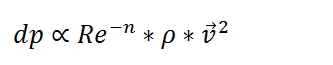
where
dp ... pressure drop
Re ... Reynolds number
n ... coefficient
r ... density
n ... velocity
The coefficient n is set for the condensate-/ fluid-side with DP34EXP and for the air-side with DP62EXP. It can be set in a range between 0 and 2.
The air flow rate is a function of the fan speed and optionally the pressure loss. Following calculation modes are provided and can be selected via FAIRFLOW.
The off-design performance of the fan and motor can either set directly via FANEFF and MOTOREFF or can be calculated as a function of the fan speed (char line: CFANEFF) and rel. motor power (char line: CMOTOREFF). As a third option, the user may specify a kernel expression in the inputs for EFANEFF and EMOTOREFF, respectively.
The performance of the condenser is in both design and off-design mode set by the steam inlet conditions and the flow rate on port 3. The total steam flow is condensed and the exit conditions correspond to that of water at the boiling point at the specified pressure on port 4 (i.e. no sub cooling).
The heat transfer is modelled as a cross-flow heat exchanger with a single pass. The calculation of the heat capacity or the necessary size is based on the NTU-effectiveness method see references (1) ,(2), and (3).
The condensate pressure is set directly on the line on port 4. It applies following equation: P3 = P4 + DP34. A minimal allowed condensate pressure can be set with PMIN. A condensation pressures lower than PMIN result in a warning message after the simulation.
The product of the overall heat transfer coefficient (K) and the transfer area (A) is a design characteristic for the heat transfer: KA = K * A. The user has the option to specify either K (overall heat transfer coefficient OHTC) or A (AREA) in design mode with method FDESIGN = 0 (Set NBAYS get per bay nominal data).
With design method FDESIGN = 1 (Set per bay nominal data get NBAYSN) KA = KAN * AREAN, and the design calculation will determine the number of bays NBAYSN to achieve the design target. In order to produce an integer number for NBAYSN, the nominal cleanliness CLFN is adjusted, representing a design margin or degradation factor. With the input for desired cleanliness CLF, the user can force the nominal cleanliness to be less than this value, which means that NBAYSN will be increased until CLFN < CLF. In off-design mode, CLFN will always be applied.
In off-design mode the condensate pressure is a function of
The user can either set the number of active bays and the fan speed manually or choose from 2 different modes to automatically set the number of active bays or the fan speed in a way to reach the desired condensation pressure as close as possible.
These modes are selected with the flag FBAYMODE.
The change in the overall heat transfer coefficient K is proportional to Re^m. It can be assumed that the heat transfer coefficient on the condensate side is much higher than that on the air side. Hence the air-end heat transfer coefficient plays the dominating role for the heat transmission coefficient.
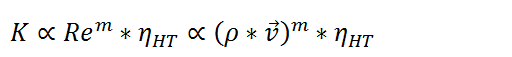
where
K ... overall heat transfer coefficient
Re ... Reynolds number
m ... coefficient
hHT ... heat transfer efficiency
r ... density
n ... velocity
The coefficient m can be set in a range between 0 and 2 for the air-side with EXP12. In addition, a heat transfer performance factor can be set for the air-side with the Parameter PFKA12 which may optionally also be read from the logic line on port 7. Alternatively, a function for the off-design performance factor can be specified in the characteristic line CPFM1M1N with the parameter M1/M1N, or a kernel expression can be defined in the input for EPFKA12.
In cooler mode, the fluid temperature is not coupled to the outlet pressure and needs to be set. In design method FDESIGN = 0 (Set NBAYS get per bay nominal data) the user has four possibilities to set the fluid exit temperature on port 4, which are selected with the flag FCOOLING.
In design method FDESIGN = 1 (Set per bay nominal data get NBAYSN), the fluid exit temperature on port 4 must be defined externally and the design calculation will determine the number of bays NBAYSN to achieve this target. In order to produce an integer number for NBAYSN, the nominal cleanliness CLFN is adjusted, representing a design margin or degradation factor. With the input for desired cleanliness CLF, the user can force the nominal cleanliness to be less than this value, which means that NBAYSN will be increased until CLFN < CLF. In off-design mode, CLFN will be applied.
The heat transfer is equivalent to that of a cross-flow heat exchanger with one pass. The calculation of the heat capacity or the necessary size is based on the effectiveness-NTU method, see references (1) ,(2), and (3).
With the flag FSIZEKA the user can specify the method to determine the heat transfer area based on the definition of the overall heat transfer coefficient which for the air cooler - in contrary to the condenser mode - is set through definition of the heat transfer coefficient for the air side (HTC12) and fluid side (HTC34), as well as the wall conductivity (LAMWALL). It is also necessary to specify the tube inner diameter (DI), the wall thickness (S_WALL) and the finned heat transfer coefficient (CFINS) to calculate the overall heat transfer coefficient.
If the method 'Set outside area' is selected, the overall heat transfer coefficient is calculated based on the user input for the parameter AREA.
The user can either set the number of active bays and the fan speed manually or choose from 2 different modes to automatically set the number of active bays or the fan speed in a way to reach the desired hot side exit temperature as close as possible.
These modes are selected with the Flag FBAYMODE.
Similar to the air cooled condenser mode above, the change in the heat transfer coefficient K is proportional Re^m. It can be assumed that the heat transfer coefficient on the fluid-side is nearly ten times higher than that on the air side.
![]()
The coefficient m is per default 0 and can be set in a range between 0 and 2 for the fluid-side with EXP34 and for the air-side with EXP12. In addition, a heat transfer efficiency factor η_HT can be set for the air-side with PFKA12, the logic line on port 7 or the char line M1M1N. For the fluid-side the efficiency factor is set with PFKA34 or the char line M3M3N. The values of both factors are minimal 0.01 and may be higher than 1.
|
FMODE |
Flag to set the calculation mode Design / Off-design = 0: Global = 1: local off-design (i.e. always off-design mode, even when a design calculation has been done globally) =-1: local design (i.e. always design mode, even when a off-design calculation has been done globally) |
|
FTYPE |
Flag to set the equipment type =0: Condenser =1: Cooler |
|
FAIRPATH |
Flag to set draft mode =0: Forced draft =1: Induced draft |
|
FDESIGN |
Flag to set the design method =0: Set NBAYS get per bay nominal data |
|
NBAYS |
Number of active bays |
|
FAIRMODE |
Flag to set the air flow design mode =0: Set DT24 (T4-T2) =1: T2 given =2: M2 given |
|
FCOOLING |
Flag to set the cooler design mode =0: Set DT14 (T4-T1) =1: T4 given =2: Q34 given =3: Effectiveness given |
|
DT24 |
T4 – T2 |
|
DT14 |
T4 – T1 |
|
Q34 |
Cooling duty Q34 |
|
EFF |
Desired effectiveness |
|
CLF |
Desired Cleanliness (design only; limits nominal cleanliness CLFN) |
|
FSIZEKA |
Flag for the sizing mode of the heat transfer area =0: Set Heat Transfer Coefficient =1: Set Outside Area |
|
AREA |
Total heat transfer surface area |
|
OHTC |
Overall heat transfer coefficient |
|
HTC12 |
Air side heat transfer coefficient |
|
HTC34 |
Fluid side heat transfer coefficient |
|
S_WALL |
Wall thickness |
|
LAMWALL |
Wall conductivity |
|
DI |
Tube inner diameter |
|
CFINS |
Ratio of the surface area with fins to that without fins |
|
FDPMODE |
Flag for the air pressure drop definition =0: Set fan pressure drop =1: Set fan electric power |
|
DPFAN |
Fan pressure drop |
|
FANPOWER |
Fan electric power |
|
DP34 |
Steam inlet or tube side pressure drop (P3 – P4) |
|
FBAYMODE |
Flag for setting the off-design mode =0: Set the number of active bays and the fan speed =1: Set the fan speed and target pressure or target temperature. The number of required bays to reach the specifications is calculated. =2: Set the number of active bays and target pressure or target temperature. The required fan speed is calculated. |
|
FPRESSURE |
Flag to set the condensate pressure mode =0: Use the value TARGETPRESSURE =1: Use the pressure value on the logic line at port 7 |
|
TARGETPRESSURE |
Target pressure for the off-design mode |
|
TARGETTEMPERATURE |
Target temperature for the off design-mode |
|
FFANSPEED |
Flag to set the fan speed mode =0: Use the value FANSPEED =1: Use the mass flow value on the logic line on port 7 |
|
FANSPEED |
Fan speed for the off design-mode |
|
FPMIN |
Flag to set the mode for the minimum condensate pressure =0: Use the value PMIN =1: Use the expression EPMIN |
|
PMIN |
Minimum allowed pressure |
|
EPMIN |
Use these expression to set the minimum condensate pressure |
|
FANSPEED_LO |
Minimum rel. fan speed before switching of one bay |
|
FANSPEED_HI |
Maximum rel. fan speed before switching on one bay |
|
EXP12 |
Off-Design Exponent for HTC12 |
|
EXP34 |
Off-Design Exponent for HTC34 |
|
DP62EXP |
Off-Design Exponent for DP62 |
|
DP34EXP |
Off-Design Exponent for DP34 |
|
FAIRFLOW |
Flag to set the off-design air flow mode =0: Volume flow is proportional to the fan speed =1: Use the char line: Rel. Fan-Speed vs. Rel. Volume Flow (CFANFLOW) =2: Use the char line: Rel. Volume Flow vs. Rel. DP (CFANCURVE) =3: Use the expression for rel. volume flow (ERELVOLFLOW) |
|
ERELVOLFLOW |
Expression for the relative volume flow |
|
FFANEFF |
Flag to set the fan efficiency off-design mode =0: Use the value FANEFF =1: Use the char line: FANEFF=FANEFFN*FN(FANSPEED) (CFANEFF) =2: Use the expression: FANEFF=FANEFFN*EFANEFF |
|
FANEFF |
Desired fan efficiency |
|
EFANEFF |
Expression for rel. fan efficiency |
|
FMOTOREFF |
Flag to set the motor efficiency off-design mode =0: Use the value MOTOREFF =1: Use the char line: MOTOREFF=MOTOREFFN*FN(RelPower)/FN(RelPower=1) (CMOTOREFF) =2: Use the expression: MOTOREFF=MOTOREFFN*EMOTOREFF |
|
MOTOREFF |
Desired motor efficiency |
|
EMOTOREFF |
Expression for the rel. motor efficiency |
|
FPFKA12 |
Flag to set the air side off-design heat transfer performance factor mode =0: Use the value PFKA12 =1: Use the enthalpy value on the logic line at port 7. =2: Use the char line CPFM1M1N =3: Use the expression: PFKA12 = EPFKA12 |
|
PFKA12 |
Off-design heat transfer performance factor on the air-side |
|
EPFKA12 |
Expression for off-design performance factor on air side PFKA12 |
|
FPFKA34 |
Flag to set the fluid side off-design heat transfer performance factor mode =0: Use value PFKA34 =2: Use the char line: CPFM3M3N =3: Use the expression: PFKA34 = EPFKA34 |
|
PFKA34 |
Off-design heat transfer performance factor on the water-/ steam-side |
|
EPFKA34 |
Expression for off-design performance factor on fluid side PFKA34 |
|
NBAYSN |
Nominal number of bays |
|
KAN |
Nominal K*A per bay - Design Heat Transfer Capability per bay |
|
AREAN |
Nominal area per bay |
|
M1N |
Nominal air flow per bay |
|
RHO1N |
Nominal air density |
|
RHO1FN |
Nominal air density after fan |
|
P3N |
Nominal steam/fluid inlet pressure |
|
H3N |
Nominal steam/fluid inlet enthalpy |
|
M3N |
Nominal steam/fluid inlet mass flow per bay |
|
HTC12N |
Nominal air side heat transfer coefficient |
|
HTC34N |
Nominal fluid side heat transfer coefficient |
|
RWALLN |
Nominal wall resistance |
|
AOFAIN |
Nominal area ratio Ao/Ai (outer surface to inner surface) |
|
AOFAMN |
Nominal area ratio Ao/Am (outer surface to average surface) |
|
DP62N |
Nominal air side pressure drop |
|
DP34N |
Nominal steam inlet/ fluid side pressure drop |
|
FANEFFN |
Nominal fan efficiency |
|
MOTOREFFN |
Nominal motor efficiency |
|
SHAFTPOWERN |
Nominal shaft power |
|
CLFN |
Nominal Cleanliness |
The parameters marked in blue are reference quantities for the off-design mode. The actual off-design values refer to these quantities in the equations used .
Generally, all inputs that are visible are required. But, often default values are provided.
For more information on colour of the input fields and their descriptions see Edit Component\Specification values
For more information on design vs. off-design and nominal values see General\Accept Nominal values
|
Characteristic line 1 |
|
R_FANEFF = f (relative FANSPEED) |
|
Characteristic line 2 |
|
V1/V1N = f (FANSPEED) |
|
Characteristic line 3 |
|
DP62/DP62N = f (VM1/VM1N) |
|
Characteristic line 4 |
|
R_MOTOREFF = f (QSHAFT/QSHAFTN) |
|
Characteristic line 5 |
|
PFKA12 = f (M1/M1N) |
|
Characteristic line 6 |
|
PFKA34 = f (M3/M3N) |
| Characteristic line 7 Name: CWINDKORR Title: Influence of the wind on the air intake flow Description: Performance factor depending on the speed of the wind |
| PFVM1 = f (VWIND) X-Axis wind speed Y-Axis Performance factor |
Component Displays
 |
Display Option 1 |
 |
Display Option 2 |
 |
Display Option 3 |
|
Click here >> Component 127 Demo << to load an example.