
EBSILON®Professional Online Documentation


(Development status: Release 11 patch 02)
|
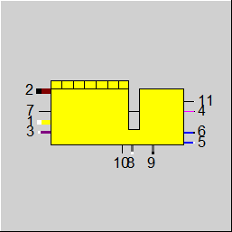
Line connections |
|
|
|
1 |
Suction air inlet |
|
|
2 |
Exhaust gas outlet |
|
|
3 |
Fuel inlet |
|
|
4 |
Power output at generator terminals |
|
|
5 |
HT cooling flow inlet |
|
|
6 |
HT cooling flow outlet |
|
|
7 |
Heat to be dissipated by radiator |
|
|
8 |
Lube oil flow in |
|
|
9 |
Lube oil flow out |
|
|
10 |
Set value for lube oil inlet temperature |
|
|
11 |
Load / desired power |
|
General User Input Values Characteristic Lines Physics Used Displays Example
This component is developed in cooperation with the company Wärtsilä and shall serve as a basis for a motor library in Ebsilon.
The module represents a unit of the components that belong to the minimum scope of supply possible.
Basically these are:
As in reality the customer cannot influence the internal configuration of these components, they are represented as a fixed unit in EBSILON as well.
The behaviour of the component is defined by characteristic lines and characteristic fields.
Other types of fluids can be used for high pressure cooling (connections 5 and 6), lubrication (connections 8 and 9) and for the fuel supply (connection 3).
The possible fluid types are set via connection point 5 or 8 or 3 on the component.
Click the connection points with the right mouse button.
The following options are displayed:
High pressure cooling (ports 5 inlet and 6): Water (liquid)
Oil (with specifiable composition)
User defined
2-phase fluid (liquid)
Salt water
Universal fluid
Binary mixture
Oil / melt (polynomial-based properties)
Change link type (inlet and outlet are adapted to the selected fluid type)
Click the connection point lubricating oil inlet.
Lube oil (ports 8 inlet and 9): Water (liquid)
Oil (with specifiable composition)
User defined
2-phase fluid (liquid)
Salt water
Universal fluid
Binary mixture
Oil / melt (polynomial-based properties)
Change link type (inlet and outlet are adapted to the selected fluid type)
Fuel supply (click on connection 3 with the right mouse button): Crude gas
Oil (with specifiable composition)
Coal / solid matter
Gas (fuel gas)
User defined
Change connection type (inlet is adapted to the selected fluid type)
There are characteristic lines for :
• the fuel demand (MW(ch) related to the lower calorific value) depending on the electric generator output, characteristic line 5
• the exhaust mass flow depending on the electric generator output, characteristic line 6
• the distribution of the low temperature heat (usable fraction) depending on the return temperature, characteristic line 7
• the distribution of the high temperature heat (usable fraction) depending on the temperature of the water between the heat exchangers, characteristic line 8
The characteristic fields define (FCALC = 0)
• the exhaust temperature behind the turbo charger depending on the electric generator output and the intake-air temperature, MXT2
• the outlet temperature of the internal cooling water at the system boundary depending on the electric generator output and the intake-air
temperature, MXTCOOLO
• the inlet temperature of the lubricating oil at the system boundary depending on the electric generator output and the intake-air temperature, MXTOILI
• the heat loss from the compressed air, MXDQAIRDUMP
The two latter temperature characteristic fields basically state the heat output that can be decoupled in the respective cooling circuit, because the internal coolant mass flow as well as the respective unspecified temperature are unalterable.
A new calculation method (FCALC = “Heat recovery heat exchangers outside component“) with a changed envelope boundary has been implemented in this component in order to increase the accuracy of the Ebsilon calculation compared to the manufacturer data. In the old mode, deviations of up to 5 percent had been detected.
Three cooling cycles have been taken as a basis in the model:
• High temperature water cooling
• Lubrication oil cooling
• Low temperature water cooling
The high temperature heat exchanger and the lubrication oil heat exchanger are affected by the shift of the envelope boundary. These were integrated into the component by means of characteristic lines. But as Ebsilon is able to represent heat exchangers much more precisely than it is possible by means of characteristic lines, these two heat exchangers have been removed from the component. When modeling, the user has to build these heat exchangers into the model, as exemplified in the sample model.
The low temperature cooling cycle is represented completely within Component 125, i.e. there are no pins to the outside for it. The heat dissipated from the engine to this cycle, though, is shown as result value QLT.
Also the (optional) air preheating is no longer treated within the component but has to be represented by a separate heat exchanger.
In this context there have also been some changes in the range of the specification values, characteristic lines, and matrices.
Specification values are
• the mass flow through the high-temperature heat exchanger (MCOOL) in contact with Pins 5 and 6 of Component 125• the mass flow through the lubrication oil heat exchanger (MOIL) in contact with Pins 8 and 9 of Component 125
• the temperature with which the water from Pin 6 of Component 125 flows into the high-temperature heat exchanger (TCOOLO)
• the set point temperature with which the lubrication oil flows from the lubrication oil heat exchanger into Pin 8 of Component 125 (TOILI).
As this temperature arises as a result of the external lubrication oil heat exchanger, it cannot be set by Component 125 but is output on a logic outlet (Pin 10) to allow
for a control (see below).• the additional heat losses (QLOSS)
Characteristic lines exist for calculation type FCALC = 1 (Heat recovery heat exchangers outside component)
• the input fuel power (CQFUEL), characteristic line 1
• the electric power (CQEL), characteristic line 2
• the heat dissipated by the lubrication oil (CQOIL),characteristic line 3
• the outlet temperature of the lubrication oil (CTOILO) at Pin 9 of Component 125, characteristic line 4
Matrices to be specified are for calculation type FCALC = 1 (Heat recovery heat exchangers outside component)
• the exhaust gas mass flow depending on load and air inlet temperature (MXM2)
• the exhaust gas temperature depending on load and air inlet temperature (MXT2)
• the heat dissipated in the high-temperature heat exchanger depending on load and air inlet temperature (MXQHT)
• the heat dissipated in the low-temperature heat exchanger depending on load and air inlet temperature (MXQLT)
The data for the Wärtsilä motors 18V50SG_A and 20V34SG_C2 are stored in the standard database.
Please note that there is an internal bypass control for the high-temperature heat exchanger, whereas for the lubrication oil heat exchanger a bypass has to be represented in the model. For this purpose, a control signal is provided at Pin 10. It indicates the required return temperature of the lubrication oil. In the design case, the heat exchanger can be designed for this temperature. In off-design mode, a bypass is controlled for setting the required temperature.
The component calculates the heat to be dissipated in the radiator using the heat balances. A minimum heat loss (QLOSSMIN) can be specified in order to prevent unrealistic results. If this is fallen below, a warning will be output.
The energy balancing is affected in the following way:
A part (result value DQCOOLH) of the total heat that the motor gives off to the high-temperature cooling cycle (result value QCWI) is used for the external high-temperature heat exchanger; the rest (DQCOOLD) has to be dissipated to the ambiance.
A part (result value DQOILH) of the total heat that the motor gives off to the lubrication oil cooling cycle (result value QOIL) is used for the external lubrication oil heat exchanger; the rest (DQOILD) has to be dissipated to the ambiance.
The total of these two losses is shown as result value QDUMP:
QDUMP = DQCOOLD + DQOILD
The compliance with the minimum heat loss (QLOSSMIN) is checked for this value.
The radiation losses QRAD result from the total energy balance of the component:
QRAD=QFUEL-QEXH- QCWI-QOIL-QLT-QLOSS-QEL
with
QFUEL= M3*NCV3 (input latent fuel heat)
QEXH = M2*H2 – M1*H1 – M3*H3
(difference from the heat dissipated by the exhaust gas and the input of (sensible) heat by air and fuel)
QLOSS: additional losses specified in the specification value QLOSS
QEL: generated electric power
The flag FOP allows to switch between normal operation (power and heat, FOP=0) and purely electric operation (FOP=1). In the latter case, the mass flows for both the external heat exchangers are set to 0.
The flag FLOAD allows to switch the load specification between
• base load from CQEL (0)
• specification of the desired power at Pin 11 (1)
• specification of the load factor at 11 (2)
The characteristic line CQEL is used for both FLOAD=0 and FLOAD=2. It specifies the electric power (as absolute value) depending on the load factor. For FLOAD=0 the power resulting for a load factor = 1 is used. For FLOAD=2 the power resulting for the load factor specified at Pin 11 (as enthalpy) is used.
For FLOAD=1 the characteristic line CQEL is not used; instead, the power specified at Pin 11 is used directly.
Simplifications
In the current state of development, the module has been simplified in several respects compared to the actual behaviour of the motor:
1.) In the case of the least favorable operating conditions, the maximum achievable motor output and thus the efficiency may be affected (“derating“). This behaviour has not been considered,
as in the vast majority of cases it is irrelevant for the operating conditions common in Germany. The derating may have the following causes:
• The methane number of the natural gas is too low (increases the propensity towards engine knocking)
• The intake-air temperature is too high (reduces the throughput of the turbo charger, increases the propensity towards engine knocking)
• The supply pressure of the natural gas is too low (reduces the fuel volume that can be filled into the cylinder)
• The calorific value of the natural gas is too low (reduces the amount of heat released in the cylinder)
• The pressure of the ambient air is too low (reduces the throughput of the turbo charger, increases the propensity towards engine knocking)
2.) Neglect of all pressure losses
3.) Neglect of the over saturation of the supercharged air
4.) No checking for critical / incorrect operating conditions
Specification of voltage, frequency and type of current in the component:
There is the option of specifying the voltage (VOLT), frequency (FREQ) and type of current (NPHAS) as the default value in the component.
The flags FVOLT and FFREQ are used to set whether the specification is to be made by the new specification values VOLT and FREQ respectively (0) or externally as a measured values on the electrical line (-1).
|
FCALC |
Flag for calculation type Like in Parent Profile (Sub profile option only) Expression =0: Heat recovery heat exchangers inside component =1: Heat recovery heat exchangers outside component (Extension) |
|
FLOAD |
Flag for load specification Like in Parent Profile (Sub profile option only) Expression =0: Base Load (from CQEL) =1: Desired power set on pin 11 (as enthalpy) =2: Part Load fraction set on pin 11 (as enthalpy), (from CQEL) |
|
FOP |
Flag for operation mode Like in Parent Profile (Sub profile option only) Expression =0: Electric power and heat =1: Electric power only |
|
MCOOL |
High temperature cooling cycle mass flow |
|
TCOOLO |
High temperature cooling cycle outlet temperature |
|
MOIL |
Lubrication oil cycle mass flow |
|
TOILI |
Lubrication oil cycle inlet temperature |
|
QLOSS |
Additional heat loss |
|
QLOSSMIN |
Minimum heat loss |
|
P3MIN |
Minimum fuel pressure (deprecated, für FCALC =0) |
|
PCOOLI |
High temperature cooling water inlet pressure |
|
TCOOLI |
High temperature cooling water inlet temperature |
|
TOILO |
Lubrication oil cycle outlet temperature |
|
CPOIL |
Oil specific heat capacity |
|
FAIRPREH |
Flag for intake air preheating Expression =0: OFF =1: ON |
|
TAIRPREH |
Preheating temperature |
|
FVOLT |
Flag for the method for specification of voltage Like in Parent Profile (Sub profile option only) Expression =0: Defined by specification value VOLT =-1: Voltage given externally on electrical outlet |
|
VOLT |
Voltage (on electric lines) |
|
FFREQ |
Flag for the method for specification of frequency Like in Parent Profile (Sub profile option only) Expression =0: Use specification value FREQ =-1: Frequency given externally on electrical outlet |
|
FREQ |
Generator frequency |
|
NPHAS |
Type of current Like in Parent Profile (Sub profile option only) Expression =0: Direct current =1: One-phase alternating |
The identification values marked in blue are reference quantities for the off-design mode. The actual off-design values refer to these quantities in the equations used.
Generally, all inputs that are visible are required. But, often default values are provided.
For more information on colour of the input fields and their descriptions see Edit Component\Specification values
For more information on design vs. off-design and nominal values see General\Accept Nominal values
|
Characteristic line 1 CQFUEL : Input fuel power QFUEL = f (Load factor) |
|
X-axis 1 load factor 1st point 2 load factor 2nd point . N load factor last point Y-axis 1 QFUEL 1st point 2 QFUEL 2nd point . N QFUEL last point
|
|
Characteristic line 2 CQEL: Electric power QEL = f (Load factor) |
|
X-axis 1 load factor 1st point 2 load factor 2nd point . N load factor last point Y-axis 1 QEL 1st point 2 QEL 2nd point . N QEL last point
|
|
Characteristic line 3 CQOIL: Heat from lubrication oil heat QOIL = f (Load factor) |
|
X-axis 1 load factor 1st point 2 load factor 2nd point . N load factor last point Y-axis 1 QOIL 1st point 2 QOIL 2nd point . N QOIL last point
|
|
Characteristic line 4 CTOILO: Lubrication oil cycle outlet temperature TOILO = f (Load factor) |
|
X-axis 1 load factor 1st point 2 load factor 2nd point . N load factor last point Y-axis 1 TOILO 1st point 2 TOILO 2nd point . N TOILO last point
|
|
Characteristic line 5 CQ3NCV: Deprecated Fuel demand per net calorific value (for FCALC = 0) Q3NCV = f (Q4) |
|
X-axis 1 Q4 1st point 2 Q4 2nd point . N Q4 last point Y-axis 1 M3*NCV 1st point 2 M3*NCV 2nd point . N M3*NCV last point
|
|
Characteristic line 6 CM2: Deprecated Exhaust gas mass flow (for FCALC = 0) M2 = f (Q4) |
|
X-axis 1 Q4 1st point 2 Q4 2nd point . N Q4 last point Y-axis 1 M2 1st point 2 M2 2nd point . N M2 last point
|
|
Characteristic line 7 CDISTHTLOW: Deprecated Distribution of low temperature heat (for FCALC = 0), LP-Heat (usable content) = f (TIM) |
|
X-axis 1 TIM 1st point 2 TIM 2nd point . N TIM last point Y-axis 1 LP-Heat (usable content) 1st point 2 LP-Heat (usable content) 2nd point . N LP-Heat (usable content) last point
|
|
Characteristic line 8 CDISTHTHIGH: Deprecated Distribution of high temperature heat (for FCALC = 0), HP-Heat (usable content) = f (T5) |
|
X-axis 1 T5 1st point 2 T5 2nd point . N T5 last point Y-axis 1 HP-Heat (usable content) 1st point 2 HP-Heat (usable content) 2nd point . N HP-Heat (usable content) last point
|
If (FAIRPREH=0 or T1>TAIRPREH)
Tref = T1
else
Tref = TAIRPREH
|
Characteristic field 1 MXM2 : (Exhaust gas mass flow) M2= f (Tref; Load factor) |
|
Characteristic field 2 MXT2 : (Exhaust gas temperature) T2= f (Tref; Load factor) |
|
Characteristic field 3 MXQHT : (High temperature cycle heat) QHT= f (Tref; Load factor) |
|
Characteristic field 4 MXQLT : (Low temperature cycle heat) QLT= f (Tref; Load factor) |
|
Characteristic field 5, Deprecated (FCALC=0) MXTCOOLO: (Outlet temperature of the internal cooling water) TCOOLO = f (Tref; Q4) |
|
Characteristic field 6, Deprecated (FCALC=0) MXTOILI: (Inlet temperature of the lubricating oil) TOILI= f (Tref; Q4) |
|
Characteristic field 7, Deprecated (FCALC=0) MXDQAIRDUMP: (Heat loss out of the compressed air) DQAIR_DUMP = f (Tref; Q4) |
1.) Constants
2.) Characteristic lines with one input variable and one output variable
The behaviour of the component is defined by characteristic lines and characteristic fields.
3.) Characteristic fields with two input variables and one output variable
MXT2 - The exhaust temperature behind the turbo charger depending on the electric generator output and the intake-air temperature
MXTCOOLO - The outlet temperature of the internal cooling water at the system boundary depending on the electric generator output and the intake-air temperature
MXTOILI - The inlet temperature of the lubricating oil at the system boundary depending on the electric generator output and the intake-air temperature
MXDQAIRDUMP - Heat loss out of the compressed air depending on the electric generator output and the intake-air temperature
The two latter temperature characteristic fields basically state the heat output that can be decoupled in the respective cooling circuit, because the internal coolant mass flow as well as the respective unspecified temperature are unalterable.
Required specifications:
1.) Electricity generation output (currently between 4840kW (50%) and 9730kW (100%))
2.) District heating water (at the inlet)
3.) Intake air
4.) Gas
Heat that cannot be decoupled due to the specified and resulting temperature conditions is dissipated via radiators in practice. In one of the next versions it will be possible to additionally specify this value.
|
All cases |
||
|
|
Q3NCV = f(Q4) from characteristic M2 = f(Q4) from characteristic M1 = M2 - M3 M6 = M5 P6-P5 = 0 If (FAIRPREH=0 or T1>TAIRPREH) HCOOLI = f(PCOOLI,TCOOLI) from material table DQCOOL_DUMP = DQCOOL-DQCOOL_WATER
|
|
 |
Display Option 1 |
Click here >> Component 125 Demo << to load an example.