

|
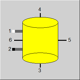
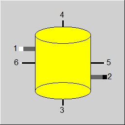
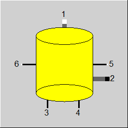
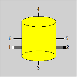
Line connections |
|
|
|
1 |
Fluid inlet |
|
|
2 |
Fluid outlet |
|
|
3 |
Logical outlet for start states (relative level as M, storage pressure as P and storage temperature as H) |
|
|
4 |
Logical outlet for end states (relative level as M, storage pressure as P and storage temperature as H) |
|
|
5 |
Control inlet for requested mass flow from storage |
|
General User Input Values Physics Used Displays Example
The direct storage component describes a tank that can be filled with a fluid. Mass and energy balance are calculated to represent a storage system for thermal energy. The special characteristic of this component is that it has transient functionality. EBSILON®Professional simulates the load or unload process of this device. In combination with the time series calculation dialog, transient calculations of thermal storage systems can be modelled.
If transient behaviour is not activated, the component simply acts as an interrupt for mass, pressure and specific enthalpy.
Nomenclature
The following terms are used to describe the storage state at different time instants:
The condition of the storage (filling level, pressure, temperature) is accessible via specification values and result values.
Two logic lines have been added to allow to access these variables also during the calculation (e.g. for control purposes).
On Outlet 3, the conditions at the beginning of the time interval are output:
On Outlet 4, the conditions at the end of the time interval are output:
Please note: a change of these variables in the course of the calculation has nothing to do with the chronological sequence but with the behaviour of the iteration.
Component 118 enables the calculation of the fluid pressure, PSTO, PNEW and the pressure at connection 2 (outlet) from the geodetic height of the fluid, which in turn depends on the fill level of the storage tank. In addition, a superimposed pressure PLOAD above the fluid column is taken into account. For this purpose, there is a value at the FPSTO switch.
For FPSTO = 2, the new fluid pressure PNEW is calculated from PLOAD and the current fill level. The pressure at port 2 is the mean value between the pressure at the start of the time step - PSTO - and the pressure at the end of the time step - PNEW.
The described pressure calculation mode (FPSTO=2) is only possible with a clear definition of the cylinder geometry or the height relevant for the calculation (FFILL=0 and FLEV=0 or FLEV=1).
The time-dependent default value PSTO can also be specified by a kernel expression. In this way, it is possible to transfer the storage pressure iteratively from the rest of the model (e.g. required when used as a start-up bottle). The coupling via the time steps to the result value PNEW is omitted in this mode.
The time-dependent specification value PSTO can additionally be specified by a Kernel expression. This allows to iteratively take over the storage pressure from the rest of the model (required e.g. for use as a start-up separator vessel). The coupling to the result value PNEW via the time steps does not apply in this mode.
With this component, the charging and discharging mass flow can be specified externally. An error message was issued if these specifications could not be met due to the current memory status.
It is also possible to specify the desired mass flow from the memory on the logic connection 5. If this value is negative, it relates (in terms of amount) to the mass flow into the storage tank. The FM switch is used to activate the specification:
• FM = -1: Both mass flows are given from outside
• FM = 1: Both mass flows are set according to the desired value at connection 5 and level
If FM = -1, the storage tank can be loaded and unloaded at the same time. If FM = 1, the discharge mass flow rate is set to 0 when charging and the charging mass flow rate is set to 0 when discharging.
When specifying the desired value for the mass flow (FM=1), the flag FTIMELIM allows to adjust what is to happen with a time series calculation if the storage system reaches the lower or upper filling level limit:
Component 118 makes it possible to specify the area-specific heat losses. The FQLOSS switch is available for this purpose. For
are differentiated..
The specification of the area-specific heat losses (FQLOSS=1) is only possible with a clear definition of the cylinder geometry or the area relevant for the loss (FFILL=0 and FLEV=0 or FLEV=1).
A reasonable estimate for the area-specific heat losses can be made on the assumption that the highest resistance to heat transfer to the environment occurs in the insulation of the cylinder. For a known insulation thickness Delta (m) and a known thermal conductivity of the insulation LAMBDA (W/mK), the area and temperature-specific loss value can be calculated as
QLOSS = LAMBDA/DELTA
can be estimated.
|
FM |
Method of determination of mass flows =-1: Mass flows given externally |
|
FTIMELIM |
Handling of limit achievement in time interval =0: Reduce power to avoid exceeding limit |
|
FLEV |
Specification of the storage lower and upper operating limit MMIN and MMAX =0: Defined relative to a "full state" (LEV-values range between 0 and 1) =1: Defined in terms of storage height MMIN=LEVMIN*ASECT*rho, MMAX=LEVMAX*ASECT*rho (LEV-values are interpreted as height) =2: Defined in terms of volume MMIN=LEVMIN*rho, MMAX=LEVMAX*rho (LEV-values are interpreted as volumes) =3: Defined in terms of mass MMIN=LEVMIN, MMAX=LEVMAX (LEV-values are interpreted as masses) |
|
LEVMIN |
Minimum level (depending on selection of FLEV, this value can be a relative value, a height, a volume or a mass) |
|
LEVMAX |
Maximum level (depending on selection of FLEV, this value can be a relative value, a height, a volume or a mass) |
|
LEVACT |
Actual level (depending on selection of FLEV, this value can be a relative value, a height, a volume or a mass) |
|
FFILL |
Definition of the "full state" if FLEV=0 is chosen =0: Mass at full load calculated from height, cross section and density (MCAP=HEIGHT*ASECT*rho) =1: Mass at full load calculated from volume and density (MCP=VCAP*rho) =2: Mass at full load specified by MCAP |
|
FRHO |
Method for calculation of the density in the storage =0: Density calculated from temperature and pressure in the storage =1: Density prescribed by parameter RHO |
|
RHO |
Density |
|
HEIGHT |
Height of the storage (if FLEV=1 or FLEV=0 in combination with FFILL=0 is selected) |
|
ASECT |
Cross section area of the storage (if FLEV=1 or FLEV=0 in combination with FFILL=0 is selected) |
|
VCAP |
Volume capacity at full state (if FLEV=0 and FFILL=1 is selected) |
|
MCAP |
Mass capacity at full state (if FLEV=0 and FFILL=2 is selected) |
| FPSTO |
Superimposed pressure =0: From constant value PSTO |
|
PSTO |
Actual pressure in storage (=pressure at outflow "2", constant over time interval) |
| PLOAD | Superimposed pressure |
|
EPSTO |
Function for pressure in storage
function evalexpr:REAL;
begin
    evalexpr:=1.0;  // [bar] required
end;
|
|
TSTO |
Actual temperature in storage (at beginning of time interval) |
|
FSTAMB |
Definition of ambient temperature =0: Given by parameter TAMB |
|
TAMB |
Ambient temperature if FSTAMB=0 |
| FQLOSS |
Definition of heat losses =0: Using QLOSSR value |
| QLS | Area and temperature specific heat loss to cylinder side surface |
| QLT | Area and temperature specific heat loss to cylinder top surface |
| QLB | Area and temperature specific heat loss to cylinder bottom surface |
|
QLOSSR |
Specific heat loss of the storage |
|
ISUN |
Index of sun component (only if FSTAMB=1) |
Generally, all inputs that are visible are required. But, often default values are provided.
For more information on colour of the input fields and their descriptions see Edit Component\Specification values
For more information on design vs. off-design and nominal values see General\Accept Nominal values
|
FLD |
Operation mode
|
|
RTIME |
Time the storage could be loaded/unloaded until the level reaches the MIN or MAX value. |
|
MACT |
Initial mass in storage |
|
MLD |
Loading mass flow (mass flow in line "1") |
|
MUNLD |
Unloading mass flow (mass flow in line "2") |
|
TIMEINT |
Final integration time interval TIMEINT=min( RTIME, RTIME(other storage components), "Time Maximum" ) |
|
MLDTOT |
Mass loaded to storage during time TIMEINT |
|
MUNLDTOT |
Mass unloaded from storage during time TIMEINT |
|
MMIN |
Minimum mass in storage |
|
MMAX |
Maximum mass in storage |
|
HSTO |
Specific enthalpy of storage at beginning of interval |
|
LEVNEW |
New level of storage (at the end of interval) |
|
MNEW |
New mass in storage (at the end of interval) |
|
PNEW |
New pressure in storage (at the end of interval) |
|
TNEW |
New temperature in storage (at the end of interval) |
|
RTAMB |
Ambient temperature used for calculation of heat losses |
|
QLOSS |
Heat losses of the storage in time interval |
|
QSLOSS |
Specific heat losses of the storage per time =QLOSS/TIMEINT |
The user has the following options to define the lower and upper limit of the storage level. If the level exceeds these limits some action in the time integration routine takes place. The user has several options to specify the MIN/MAX values of the storage. In the end, only mass based values MMIN and MMAX are used. The same specification values LEVMIN, LEVMAX are used for the user input. Via flag FLEV the physical meaning of these values can be changed (Note that given values in LEVMIN and LEVMAX are not transferred into the new unit if the flag FLEV is changed). If the user enters the limits not in terms of mass values (FLEV=3) the program calculates the corresponding MMIN and MMAX value.
The first option is to directly specify the MIN/MAX values by
Since MMIN and MMAX are specification values the limits have a constant value independent of the thermal state in the system. The other options allow the user to fix a certain level or volume as a lower and upper limit. Due to the state dependent density (if not constant density rho=RHO is selected by FRHO=1) the resulting mass limits MMIN and MMAX will depend on the temperature TSTO (and possibly pressure PSTO) at the beginning of the interval. This might be useful if the storage has a constant volume that can have a mass capacity dependent on the density of the fluid.
The remaining options are
In all cases the density rho can be given as
Thus, the calculated limits MMIN and MMAX are constant in the following combinations:
Component 118 offers in cooperation with the EBSILON®Professional time series calculation the possibility for transient simulation. By model variable "Time handling" (in dialog "Extras" ->"Model Options" ->"Simulation" ->"Transient" ->Combo box "Time handling") the user can select three modes:
Depending on the transient calculation settings (see last section) the time interval over which integration is performed is derived by one of the methods:
Please note that the calculation of the time interval is based on the values at the beginning of the time interval. Especially, the limits are evaluated based on the storage density at the beginning of the time interval. In case the thermal state of the storage changes due to a change of enthalpy/temperature the new density is not considered for the calculation of the MIN/MAX values.
During the integration time interval the incoming and out flowing mass flow MLD (mass flow load) and MUNLD (mass flow unload) are constant. Thus, the new mass in the storage is calculated as
MNEW = MACT + MLD * TIMEINT - MUNLD * TIMEINT .
Values MLD * TIMEINT and MUNLD * TIMEINT are provided to the user as result values MLDTOT and MUNLDTOT.
Since the detailed configuration of the storage system is not known to the program an assumption is used to calculate the final energetic state. It is assumed that, in a first step, the storage is loaded with mass flow MLD and enthalpy HLD, thus
H_STEP1 = (MACT * HSTO + MLD * HLD * TIMEINT) / (MACT + MLD * TIMEINT)
In a second step the heat losses to the surrounding are imposed. Heat losses are calculated from
QLOSS = QLOSSR*( 0.5 * (TSTO+TNEW) - TAMB ) * TIMEINT
where TSTO is the actual temperature of the storage (at the beginning of the interval) and TNEW=T(PNEW, HNEW) is the new temperature of the storage. The enthalpy H_STEP1 is corrected by the heat losses as
HNEW=H_STEP1*(MNEW) - QLOSS
The last two equations are solved in an iterative procedure to find a consistent new state HNEW.
The third step in the calculation procedure is the unload process, where mass of enthalpy 0.5*(HST0+HNEW) is taken out of the storage.
The pressure in the storage and the unload line "2" is user-defined at parameter PSTO. The pressure at inflow line "1" does not have any impact on the calculation procedure.
EBSILON®Professional offers, besides the conventional "calculate" functionality, also the option to simulate a time series. This feature is especially intended to be used in conjunction with the storage component 118. Within the time series dialog (short TSD) the user prescribes at least a value for LEVACT. When time series calculation is activated as transient calculation mode EBSILON®Professional automatically writes this value into component 118 and performs a calculation over the time interval defined by model variable "time handling". The result values like new level LEVNEW and temperature TNEW are then read by the TSD in the corresponding column. In case the temperature in the storage changes over time by the inflowing mass the temperature at the end of the time interval can be written into component 118 for the next time step.
If the storage reaches its minimum or maximum level within the integration time interval an additional line will be inserted in the TSD. The new line has the time stamp of the instant the storage reaches its limit. The model has to guarantee that mass flows are redirected when the storage has run full or empty.
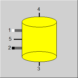 |
Display Option 1 |
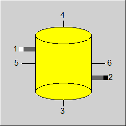 |
Display Option 2 |
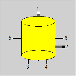 |
Display Option 2 |
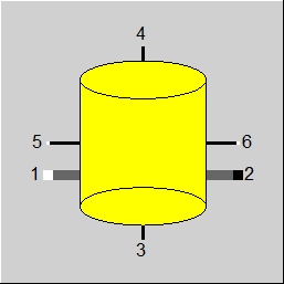 |
Display Option 4 |
 |
Display Option 5 |
 |
Display Option 6 |
 |
Display Option 7 |
 |
Display Option 8 |
Click here >> Component 118 Demo << to load an example.