EBSILON®Professional Online Documentation


|
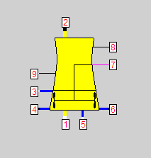
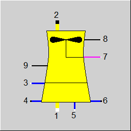
Line connections |
or (if FTYPEFAN = 1) |
|
|
1 |
Air Inlet |
|
|
2 |
Air Outlet |
|
|
3 |
Cooling Water Inlet |
|
|
4 |
Cooling Water Outlet |
|
|
5 |
Makeup Inlet |
|
|
6 |
Blow-down |
|
|
7 |
Fan Electrical Power |
|
|
8 |
Logic-inlet, Control inlet for performance factor (PACKPERF) |
|
|
9 |
Logic-inlet, Control inlet for reduction of fan speed (T4MIN) |
|
General Transient modeling User Input Values Physics Used Displays Example
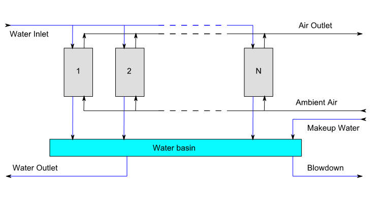
Component 112 simulates a mechanical draft cooling tower with a counter current wet cooling zone. The wet cooling zone model is based on the Merkel equation (e.g. VDI Wärmeatlas, section Mj).
There is as of Release 11 an identification mode for these cooling towers.
The flag FIDENT allows to control whether
• the cooling water outlet temperature T4 is to be calculated (FIDENT=0)
• the cooling water outlet temperature T4 is to be specified, and the air flow is to be calculated (FIDENT=1)
• the cooling water outlet temperature T4 is to be specified, and the Merkel number is to be calculated (FIDENT=2)
It is also possible to specify a wind correction.
Also, a kernel expression can be specified for the packing characteristic factor C, the performance factor K, and the wind correction.
Now the Merkel cooling towers can also be used in the INTMAT mode (integration of the material data into the equation system). Thus for models containing these components a material data reconciliation is possible too.
Annotation
There is a performance factor PACKPERF by means of which a change of the cooling tower performance can be simulated. This parameter has been made accessible via a logic line, so that an adjustment is possible.
Component 112 enables the modeling of transient regimes (time-dependent computations). This type of calculation is activated with the switch FINST.
A cooling tower features transient behavior mostly in the water basin which acts as a big water storage. The wet zone with fill or packing material also features some significant mass and acts as indirect storage delaying the cooled water temperature changes e.g. at load changes. Finally, the cooling tower shell wall also acts as an indirect storage influencing however only the air outlet state.
Cooling tower transient computations are possible for drain mode (FCIRC=1) and without hybrid mode (FHYBRID=0) only. In cooling tower transient computations the air outlet humidity is always computed (FHUM=1).
The user input values for the transient modeling are classified in the following groups.
Water basin definition - here the water basin geometric details are specified. The water basin transient mass and energy balance is computed assuming homogeneous mixing of water inside the basin. Depending on the flag value FSPIN one can either specify the water basin level (FSPIN=0) or compute the level specifying both the inlet and the outlet water mass flow (FSPIN=1).
Fill or packing material definition - here the geometric and material details of the fill or packing material (wet zone) are specified. The fill or packing material part is defined by the volume of the wet zone WZVOL, the void volume fraction PHI (i,e, the volume portion of the wet zone not occupied by the fill or packing material) as well as the fill or packing material specific surface area FV.
Heat transfer coefficients - in this group the heat and mass transfer coefficients, in particular for the simulation of the evaporation and the heat transfer in the wet zone, are specified. The heat transfer between water and air is controlled by the coefficient ALPHIWAN at Design conditions (defined by the air to water ratio) and is scaled by the corresponding parameters PACKFACT, PACKEXP, PACKPERF at off-design conditions. The mass transfer (water evaporation) is controlled by the coefficient BETAWAN at Design conditions and is scaled by the corresponding parameters PACKFACT, PACKEXP, PACKPERF at off-design conditions. There are two alternatives to specify the mass transfer coefficient. One can either specify the value of BETAWAN directly or by specifying the value of ALPHIWAN and the Lewis factor LEF defined as
\[ Le_f = \frac{\alpha}{\rho \beta c_p} \]
Here \(\alpha\) and \(\beta\) are the heat and mass transfer coefficients respectively. \(\rho\) and \(c_p\) are the air density and heat capacity.
Shell wall material definition - here the geometric and material details of the cooling tower shell wall are specified.
After spefifying all geometric details of the cooling tower one can match the results of the steady state Merkel equation model implemented in the component 112 for the wet zone by adjusting the values of ALPHIWAN, BETAWAN (or LEF) at steady state conditions.
In case of identification calculation - FIDENT > 0 - the values of the heat and the mass transfer coefficient water to air (\(\alpha\) and \(\beta\)) are adjusted to match the specified temperature T4.
| FINST |
Instationarity mode =0: Transient solution (time series or single calculation) =1: always steady state solution |
|
FFU |
Switch (on/off =0: Off (No Air calculations, set DT34N = T3-T4) =1: On |
|
DT34N |
Cooling range (Only for FFU = 0) |
|
FMODE |
Calculation mode (design / off-design) =0: Global = 1: local Off-Design =-1: local Design |
|
FIDENT |
Identification mode =0: None = 1: T4 given, identify Airflow = 2: T4 given, identify Merkel Number |
|
FWETZONE |
Switch for wet zone mode =0: Set cooling water outlet temperature T4 =1: wet-zone temperature approach =2: Merkel number (Me) =3: NTU (NTU = Me * M_Water_in / M_Air_dry_in |
|
PWETZONE |
Parameter for wet-zone wet-zone temperature approach (for FWETZONE=1) Merkel number (for FWETZONE=2) NTU (for FWETZONE=3) |
|
AWR |
Dry Air / Water Ratio, Design |
|
FPACKFACT |
Flag for Packing characteristic factor C (off design) =0: Internally by the specification value =1: PACKFACT= Port_8.P/(1 bar) =2: Expression EPACKFACT |
|
PACKFACT |
Packing-Characteristic Factor (C), off design |
|
EPACKFACT |
Expression for Packing-Characteristic Factor (C) |
|
PACKEXP |
Packing-Characteristic Exponent (M), off design |
|
FPACKPERF |
Specification of performance factor , off-design =0: Internally by the specification value =1: PACKPERF= Port_8.H/(1 kJ/kg) =2: Expression EPACKPERF |
|
PACKPERF |
Packing-Characteristic Performance Factor (K), off design |
|
EPACKPERF |
Expression for PACKPERF |
|
FMERKEL |
Switch for Merkel equation =0: Standard Merkel Equation =1: Enhanced Merkel Equation |
|
FHUM |
Handling of wet-zone outlet humidity =0: wet-zone outlet relative humidity is user input =1: wet-zone outlet relative humidity will be calculated |
|
PHIWZO |
wet-zone outlet relative humidity (FHUM=0) |
|
DRIFT |
Drift loss fraction |
|
FCIRC |
Switch for water circulation type =0: Closed circulation. Determine makeup and purge flow rate via the parameter COC =1: Open circulation. No makeup and purge flow |
|
COC |
Cycles of concentration in a closed circulation loop Hint: According to VGB R 455 P is COC = makeup water / purge water = Z/A This is a simplification that is not valid for components 111/112, because here the calculation is based on the real increase in concentration of salts under consideration of drift losses (DRIFT). |
|
NBAYS |
Number of bays active (Design) |
|
FSPECFAN |
Off-design calculation mode for fan speed =0: manual input =1: reduce fan speed to have Wet zone water temperature outlet > T4MIN (in off-design) =2: reduce fan speed to have Wet zone water temperature outlet > H9 (in off-design) |
|
T4MIN |
Minimum wet zone water exit temperature (FSPECFAN=1 or 2) |
|
DTBAND |
Switch hysteresis (FSPECFAN=1 or 2) |
|
NBAYSH |
Number of bays with reduced volume flow |
|
NBAYSOFF |
Number of bays shut off (water-side bypass) |
|
FTYPEFAN |
Fan type =0: Induced draft =1: Forced draft |
|
DP12 |
Air side pressure drop |
|
FRVMH |
Reduced volume flow fraction |
|
EFFFANN |
Fan efficiency at nominal volume flow |
|
EFFFANH |
Fan efficiency at reduced volume flow |
|
LGEARN |
Gear losses (fraction) at nominal volume flow |
|
LGEARH |
Gear losses (fraction) at reduced volume flow |
|
EFFMOT |
Motor efficiency |
|
FCFWIND |
Specification of wind correction factor =0: None =1: value CFWIND =2: value CWTDT =3: Airflow factor = Port_8.M/(1kg/s) =4:Cooling water outlet offset = Port_8.M/(1 kg/s)*(1K) =5: Char Line lookup CWINDAIRFLOW, wind speed x = Port_8.M/(1 kg/s)*(1 m/s) =6: Charlie lookup CWINDCWTDT, wind speed x = Port_8.M/(1 kg/s)*(1 m/s) =7: Expression ECFWIND corrects airflow (factor) =8: Expression ECFWIND corrects cooling water temperature (offset) |
|
CFWIND |
Wind correction factor |
|
CWTDT |
Wind correction temperature offset for cooling water outlet |
|
ECFWIND |
Expression wind correction factor |
|
FHYBRID |
Switch for hybrid mode =0: Off =1: Manual input =2: Set margin to plume formation (temperature approach) |
|
MGNPLUME |
margin to plume formation (FHYBRID=2) |
|
FHX |
Switch for heat exchanger mode =0: Off =1: Effectiveness =2: Temperature change =3: Area |
|
PHX |
Heat exchanger parameter Temperature change (if FHX=2) Area (if FHX=3) |
|
WATRAT |
Dry zone/total water - flow ratio |
|
AIRRAT |
Dry zone/total air - flow ratio |
|
KAIR |
Air side heat transfer coefficient |
|
KWAT |
Water side heat transfer coefficient |
|
FOUL |
Fouling factor |
|
PLGASEXP |
Off-design exponent gas side for heat transfer coefficient |
|
PLWATEXP |
Off-design exponent water side for heat transfer coefficient |
|
HXFRAC |
Active fraction of heat exchanger (Off-Design) |
| FINIT |
Flag: Initializing state =0: Global, which is controlled via global variable "Transient mode" under Model Options =1: First run -> Initializing while calculating steady state values |
| SHEIG | Shell height |
| SVOL | Shell volume |
| THWALL | Shell wall thickness |
| RHOS | Density of the shell wall material |
| LAMS | Heat conductivity of the shell wall material |
| CS | Heat capacity of the shell wall material |
| NFLS | Number of points in flow direction: dry zone |
| WZVOL | Wet zone volume |
| PHI | Free cross section fraction |
| FV | Outer surface to volume ratio |
| RHOFM | Density of fill or packing material |
| LAMFM | Heat conductivity of fill or packing material |
| CFM | Heat capacity of fill or packing material |
| NFLWZ | Number of points in flow direction: wet zone |
| FSPIN |
Transient balance calculation mode 0: Liquid level given, mass flows computed 1: Mass flows given, liquid level computed |
| VF | Liquid volume fraction (liquid level) at the end of the time step |
| VMIN | Volume at liquid volume fraction value 0 |
| VMAX | Volume at liquid volume fraction value 1 |
| FLVCALC |
Liquid volume calculation mode 0: linear between VMIN and VMAX 1: Using ELV |
| ELV | Function for the liquid volume computation |
| TWBEG | Temperature in water basin at time step begin (relevant for transient time steps only) |
| ALPHIS | Inner heat transfer coefficient between air and shell wall |
| ALPHIFP | Inner heat transfer coefficient between water and fill or packing material |
| ALPHIWAN | Heat transfer coefficient water to air (nominal value) |
| FCALCMT |
Mass transfer coefficient water to air calculation 0: compute mass transfer coefficient value using Lewis factor input value (LEF) 1: use directly BETAWAN value and Off-design factors and exponents |
| LEF | Lewis factor input value |
| BETAWAN | Mass transfer coefficient water to air (nominal value) |
| ALPHO | Outer heat transfer coefficient (to ambient) |
|
AWRN |
Air to water ratio (nominal) |
|
MERKELN |
Merkel number (nominal) |
|
DP12N |
Air side pressure drop (nominal) |
|
RHO1N |
Ambient air density |
|
PHI1RAT |
Ambient air humidity ratio |
|
PHI2RAT |
Air outlet humidity ratio |
|
RHO2 |
Air outlet density |
|
M2N |
Outlet air flow (nominal) |
|
M1N |
Inlet air flow (nominal) |
|
MDRYWZ |
Wet zone dry air mass flow (nominal) |
|
MAIRHXN |
Heat Exchanger air mass flow (nominal) |
|
MWATHXN |
Heat Exchanger water mass flow (nominal) |
|
KNAIR |
Air side heat transfer coefficient (nominal) |
|
KNWAT |
Water side heat transfer coefficient (nominal) |
|
AHX |
Heat exchanger area (nominal) |
|
NBAYSN |
Number of Bays (nominal) |
|
VMSTACK |
Stack volume flow (nominal) |
The identification value marked in blue is a reference value for off-design calculations. The actual off-design values refer to the values used in the equations.
Generally, all inputs that are visible are required. But, often default values are provided.
For more information on colour of the input fields and their descriptions see Edit Component\Specification values
For more information on design vs. off-design and nominal values see General\Accept Nominal values
|
Characteristic Line 1, CWINDAIRFLOW: CF(air mass flow) = f (wind speed) CF = Correction factor |
|
X-Axis 1 wind speed 1st point |
|
Characteristic Line 2, CWINDCWTDT: dT (cooling water temperature) = f (wind speed) |
|
X-Axis 1 wind speed 1st point Y-Axis 1 dT (cooling water temperature) 1st point |
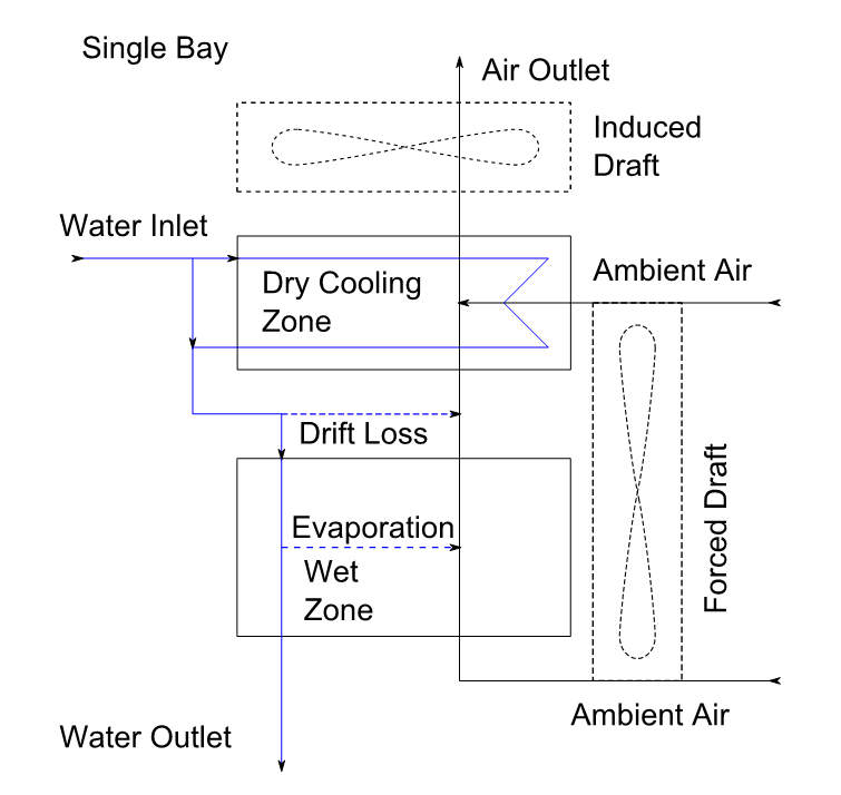
The mechanical draft cooling tower consists of multiple bays with a common water basin. Each bay consists of three zones. These zones are the wet cooling zone, the (optional) dry cooling zone and the fan.
The core to the model of the wet cooling zone is the so-called Merkel Equation [VDI Wärmeatlas, 9th ed., Chapter Mj] which describes the process of combined heat and mass transfer between the water and the air flow through the packing:
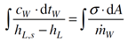
The left-hand part of the equation (the so-called Merkel-Number) describes the ratio of thermal duties to reach the desired cooling duty (with the enthalpy difference between saturation and the respective condition of the air as basis) while the right-hand side reflects the properties of the packing and the operating mode of the cooling zone.
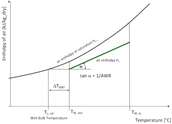
In the design mode, the user can specify through the parameters for the calculation mode FWETZONE and the respective parameter value PWETZONE if the characteristics of the cooling zone shall be pre-defined (either as Merkel-Number or NTU Number which is equal Me/AWR), or if it shall be calculated from inputs of either the water exit temperature or the approach to the wet bulb temperature of the air.
In order to model also hybrid cooling towers, which are used to avoid plume formation, the dry cooling zone can be activated by selecting the hybrid mode in the parameter FHYBRID.
In design mode, the distribution of the cooling duty between the dry and the wet zone of the hybrid cooling tower will be set either by definition of the air and water flow ratios or by the desired margin to plume formation (specified in degrees difference to the dew point).
In off-design mode, the air distribution will be calculated based on the definition of the fan operation (number of fans at half-speed or off, respectively) and the pressure loss characteristics.
The physics of the dry zone are modelled according to the rules for a normal air-water cross-flow heat exchanger, the physics of the wet cooling zone according to the rules of Merkel's equation.
The part-load performance of the wet zone is a characteristic of the Merkel number as a function of the dry air to water ratio.
The energy balance of the common water basin including the make-up water determines the final exit temperature of the cooled water stream.
The Merkel Number will be calculated, by integration of the Merkel equation.
Find the corresponding water outlet temperature to get the desired Merkel number.
Via the relationship: Me = MeDesign * K*C*(AWR/AWRDesign)m the actual Merkel number will be calculated. Then a solver finds the corresponding water outlet for this Merkel number. K, C and m are defined as PACKPERF, PACKFACT and PACKEXP.
If the wet zone outlet humidity is set by the user (FHUM=0) the Merkel number can be determined by numerical quadrature. An Implementation of algorithm 699 from TOMS; TRANSACTIONS ON MATHEMATICAL SOFTWARE, VOL. 17, NO. 4, DECEMBER, 1991, PP. 457-461; is used.
If the wet zone outlet humidity is calculated (FHUM=1) a System of ordinary differential equations needs to be solved. Here a Runge-Kutta Method of order 5 is used (Dormand-Prince).
The heat exchanger is modelled as single pass with the NTU-Effectiveness Method. (VDI Wärmeatlas, Section Ca; „Compact Heat Exchangers by W.M. Kays and A.L. London)
The Off-Design correlation for the heat transfer coefficients is
for the air-side:
k Gas Off-Design = k Gas Design *(v Gas Off-Design / v Gas Design)m1 (Default m1=0.8, m1 corresponds to PLGASEXP)
for the water side:
k Water Off-Design = k Water Design *(v Water Off-Design / v Water Design)m2 (Default m2=0.8, m2 corresponds to PLWATEXP)
Water density is considered constant
In design mode, air flow and pressure drop are user input (AWR and DP12).
The volumetric flow through the fan will be calculated.
The model assumption is a constant volumetric flow rate at nominal fan speed.
At reduced fan speed the volumetric flow rate will be scaled by the parameter FRVM.
The relationship for the pressure drop is described by the following equations:
with rho = density, and A = cross-sectional area:
![]()
and elimination of  leads to the final off-design correlation for the pressure drop:
 |
Display Option 1 |
Click here >> Component 112 Demo << to load an example.