
EBSILON®Professional Online Documentation


|
Line connections |
|
|
|
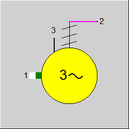
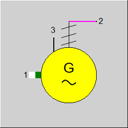
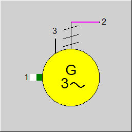
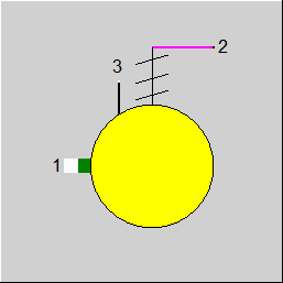
1 |
Power inlet at Shaft |
|
|
2 |
Power outlet at terminals |
|
|
3 |
Logic line (Control line inlet ) for frequency (as M), H2-pressure or voltage (as P),Efficiency (as H), power factor cos phi (as NCV) |
|
General User Input Values Displays
Component 11 is used to model a generator.
In the design mode, the generator efficiency must be specified.
In the Generator, the nominal value of the generator efficiency can also be specified as enthalpy on the logic inlet (Pin 3) instead of in the specification value ETAGN, allowing this value to be controlled too. The flag FETAGN serves to define which specification is to be used.
The off-design performance is defined by characteristic lines. These characteristic lines consist of
These characteristics provide the dependency of the generator efficiency on the given mechanical shaft power.
For the efficiency of the generator, an EbsScript function in the specification field EADAPT can be used (see Release 9, Kernel expressions, chapter 3.2).
In the standard value database, the values for the generator efficiency and the interdependence of load and cos phi have been updated. Data records for the magnitudes 83 and 277 MW are available. By default, the 83 MW values are loaded. The curves used up to Release 8 are also available. When loading models generated with Release 8, the values are not changed.
Double lookup of characteristic fields:
To ensure consistency between the design and off-design calculations, characteristic lines have to go through point (1,1). This is not difficult for simple characteristic lines. For a characteristic field, i.e. a set of characteristic lines depending on one parameter, not all characteristic lines of the set can go through (1,1). The corresponding prerequisite is here: one characteristic line in the set has to go through (1,1), and this must be the one that corresponds with the design value of the parameter.
As the characteristic field is not always present in this form, a manual (e.g. Excel-based) conversion used to be necessary in certain cases. For reasons of simplification, the double lookup has therefore been introduced, initially for the generator (Component 11).
The advantage is that the user no longer has to care if and where the value (1,1) occurs in their characteristic field. The trick is that the characteristic field is activated twice for the off-design calculation: once with the design values and once with the current values. The quotient from both results of the characteristic field is then used as characteristic field factor for the off-design calculation. For this, however, it has been necessary to introduce nominal values for the respective quantities (in the case of the generator for cos(phi), hydrogen pressure, and generator frequency).
To use this feature with the generator, the flag FCHR has to be set to 2 (“Double lookup (for not normalized characteristics)“).
Logic inlet (Connection point 3) for controlling component properties
(see also : Editing components --> Ports)
To make component properties like efficiencies or heat transfer coefficients (variation quantity) accessible from the outside (for control or reconciliation) it is possible to place the respective value on an auxiliary line as an indexed measured value (specification value FIND). In the component, the same index must then be entered as specification value IPS (component 11: IPSCOS,IPSH2P, IPSGENF).
It is also possible to place these values (measurement points) on a logic line that is directly connected to the component.
please see
FCOS=2, Variation variable: COSPHI, Cos(phi), dimension: mass flow on control inlet)
FH2P=2, Variation variable: H2P, H2-pressure, dimension: pressure on control inlet)
FGENF=2, Variation variable: GENF, Frequency, dimension: enthalpy on control inlet
The advantage is that the allocation is graphically visible, and errors (e.g. when copying) are thus avoided.
Specification of Frequency, Current, Voltage, and Phase
In the generator, the specification values COSPHI (for the power factor) and GENF (for the frequency) as well as the new specification value VOLT (Voltage) are used for specifying these variables.
For the specification values to be used, the flags FCOS, FGENF, and FVOLT are to be set accordingly.
In this case, the current is calculated from the output. The positive algebraic sign is used for the phase.
Display Formats :
Generator: Graphical symbols can be displayed instead of or in addition to the letter “G”. (see Component Displays).
Note for the FCOS / FGENF switches
If the flags FCOS and FGENF respectively are set accordingly, the specification values COSPHI and GENF will be transferred (as of Release 12) to the electric line.
As in Release 11 the default setting for these flags was “not used“, no changes occur for these flags.
For models created with older versions of Ebsilon where the setting “not used” did not exist, an unintended transfer of the power factor and the frequency to the electric line may occur.
Usually this has no consequences. If, however, start values for mass flow or pressure were used on the shaft and electric line respectively (which was required in former versions
of Ebsilon), double entries may occur, but these are easy to eliminate by removing the unnecessary specifications.
Note: Result value RGENFREQ
From this release this value (RGENFREQ) has the unit frequency - EBSILON standard unit 1 / min. The user can change the display unit to display the frequency in Hz.
|
FETAGN |
Specification of generator efficiency Like in Parent Profile (Sub Profile option only) Specification of generator efficiency |
|
ETAGN |
Generator efficiency (nominal) |
|
FCHR |
Flag for usage of char line Like in Parent Profile (Sub Profile option only) =1: Simple lookup (for characteristics normalized to design parameters) =2: Double lookup (for not normalized characteristics) |
|
FCHRX |
x-Values of the Characteristic Lines |
|
FCOS |
Handling of power factor (cos phi) to be used for characteristics and result values Like in Parent Profile (Sub Profile option only) =0: Specification value COSPHI is used |
|
COSPHI |
Power factor cos phi |
|
IPSCOS |
Index of the pseudo measurement point for power factor cos phi |
|
FH2P |
Handling of H2 pressure Like in Parent Profile (Sub Profile option only) =0: Specification value H2P is used |
|
H2P |
Hydrogen pressure in the generator casing |
|
IPSH2P |
Index of the pseudo measurement point for H2 pressure |
|
FGENF |
Handling of generator frequency-default Like in Parent Profile (Sub Profile option only) =0: Specification value GENF is used |
|
GENF |
Generator frequency |
|
IPSGENF |
Index of the pseudo measurement point generator frequency |
|
FMODE |
Flag for calculation mode =0: GLOBAL =1: local off-design =-1: local design |
|
FVOLT |
Handling of voltage Like in Parent Profile (Sub Profile option only) Expression =0: Defined by specification value VOLT |
|
VOLT |
Voltage (on electric line) |
|
FADAPT |
Flag for adaptation polynomial / adaptation Function Like in Parent Profile (Sub Profile option only) Expression =0: Not used and not evaluated =1: Correction factor for characteristics: the value for the generator efficiency determined from the characteristic is multiplied with the value of the adaptation polynomial =2: Substitute for characteristic: ETAGN is multiplied with the value of the adaptation polynomial, the characteristic is not used =1000: Not used, but ADAPT evaluated as RADAPT (Reduction of the computing time) =-1: used result of EADAPT-function as correction factor for characteristics =-2: used result of EADAPT-function as replacement factor for characteristics =-1000: Not used, but EADAPT evaluated as RADAPT (Reduction of the computing time) |
|
EADAPT |
Adaptation Function |
|
Q1N |
Power at generator inlet (nominal) |
|
COSPHIN |
Power factor (nominal) |
|
H2PN |
H2 pressure (nominal) |
|
GENFN |
Generator frequency (nominal) |
The parameters marked in blue are reference quantities for the off-design mode. The actual off-design values refer to these quantities in the equations used.
Generally, all inputs that are visible are required. But, often default values are provided.
For more information on colour of the input fields and their descriptions see Edit Component\Specification values
For more information on design vs. off-design and nominal values see General\Accept Nominal values
Previously, all characteristic lines always referred to
the ratio of prevailing shaft power to nominal shaft power.
As, however, many manufacturers have their characteristic lines refer to the electrical power, Ebsilon now allows to use the flag FCHRX to switch over from Q1/Q1N (FCHRX=1) to Q2/Q2N (FCHRX=2).
|
Characteristic line 1 : Electrical efficiency ETAG/ETAGN = f (Qx/QxN,PHI1) PHI=COS(PHI) |
|
X-Axis 1 Qx/QxN 1st point |
|
Characteristic line 2 : Electrical efficiency ETAG/ETAGN = f (Qx/QxN,PHI2) |
|
X-Axis 1 Qx/QxN 1st point |
|
Characteristic line 3 : Electrical efficiency ETAG/ETAGN = f (Qx/QxN,PHI3) |
|
X-Axis 1 Qx/QxN 1st point |
|
Characteristic line 4 : Electrical efficiency ETAG/ETAGN = f (Qx/QxN,PHI4) |
|
X-Axis 1 Qx/QxN 1st point |
|
Characteristic line 5 : Electrical efficiency ETAG/ETAGN = f (Q1/Q1N,PHI5) |
|
X-Axis 1 Q1/Q1N 1st point |
|
Characteristic line 6 : Electrical efficiency ETAG/ETAGN = f (Qx/QxN, H2P_1) H2P=p(H2) |
|
X-Axis 1 Qx/QxN 1st point |
|
Characteristic line 7 : Electrical efficiency ETAG/ETAGN = f (Qx/QxN, H2P_2) |
|
X-Axis 1 Qx/QxN 1st point |
|
Characteristic line 8 : Electrical efficiency ETAG/ETAGN = f (Qx/QxN, H2P_3) |
|
X-Axis 1 Qx/QxN 1st point |
|
Characteristic line 9 : Electrical efficiency ETAG/ETAGN = f (Qx/QxN, H2P_4) |
|
X-Axis 1 Qx/QxN 1st point |
|
Characteristic line 10 : Electrical efficiency ETAG/ETAGN = f (Qx/QxN, H2P_5) |
|
X-Axis 1 Qx/QxN 1st point |
|
Characteristic line 11-19 : Electrical efficiency ETAG/ETAGN = f (Qx/QxN, GENF_1...9, EBSILON standard unit 1 / min) GENF (Hz) |
|
X-Axis 1 Qx/QxN 1st point |
|
all cases |
||
|
M2*H2 = M1*H1 * ETAGN * f 1(Qx/QxN) * f2(Qx/QxN) * f3(Qx/QxN) |
||
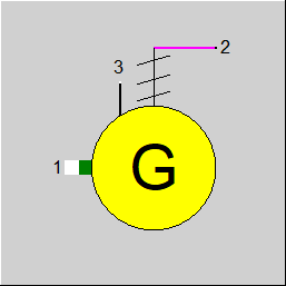 |
Display Option 1 |
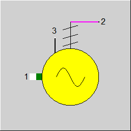 |
Display Option 2 |
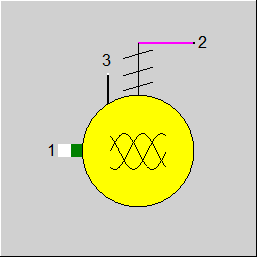 |
Display Option 3 |
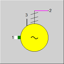 |
Display Option 4 |
 |
Display Option 5 |
 |
Display Option 6 |
 |
Display Option 7 |
 |
Display Option 8 |
Click here >> Component 11 Demo << to load an example.