
EBSILON®Professional Online Documentation


|
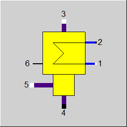
Line connections |
|
|
|
1 |
Cooling medium inlet |
|
|
2 |
Cooling medium outlet |
|
|
3 |
Exhaust steam inlet |
|
|
4 |
Condensate outlet |
|
|
5 |
Secondary condensate inlet |
|
|
6 |
for future use |
|
General User Input Values Characteristic Lines Physics Used Displays Example
This component differs from component 7 by using a binary mixture at the inlet on the hot side. Because such a mixture does not have a fixed condensation temperature, but at first the solvent condenses and at lower temperatures eventually also the cooling agent, the outlet temperature of the cooling water can be above the condensation temperature range in the case of this component.
Flag FSPECPD:
In Release 13 it is possible specify the design pressure (and also the start value for the internal iteration in off-design) in the component as specification value P3N.
The specification is controlled via the flag FSPECPD (see "User Input Values").
Flag FDQLR
It is possible to use the FDQLR flag to define how DQLR (factor for modeling heat losses) should be interpreted.
External Specification of the Pressure of the Auxiliary Condensate
Since the auxiliary condensate is at the same pressure level as the condensate, it is necessary during modeling to install a control valve or a condensate valve on the auxiliary condensate line in to decrease the pressure to the Preheater / Heating condenser level.
To simplify the modeling, there is now a mode “P5 given externally“ that can be set by means of the flag FP5. This mode allows to connect a line with a higher pressure on
Pin 5. Within the component, the auxiliary condensate is then reduced to the preheater / heating condenser pressure. The result is the same as with an external control valve.
This mode is the default setting for newly inserted components. For existing models, FP5 is set to “P5=P3“.
Pressure drop limitations in off-design (Extras --> Model Options--> Calculation -->Relative pressure-drop maximum) :
As the pressure drop rises quadratically with the mass flow, pressure drops that are significantly too high can quickly arise in the event of a transgression of the nominal mass flow. These will then cause phase transitions and convergence problems. For this reason, pressure drop limitations have been installed.
Performance factor RPFHX
The quotient from the current value for k*A (result value KA) and the k*A expected in the respective load point due to the component physics and characteristic lines respectively (result value KACL) serves to assess the condition of a heat exchanger.
The quotient KA / KACL is displayed as a result value RPFHX.
Treatment of mixtures: Note about the result values:
In the process of the unification of this component with Component 7, an inconsistency when using water/lithium bromide as working fluid was noticed. As no lithium bromide exists in the gaseous phase, this component has to condense pure steam in this case and should therefore behave exactly like Component 7. The reference temperature for specification value DT3S2N should therefore also be the boiling temperature of water. That was not so, in this case the temperature at Inlet 3 was used. This has been corrected. The error message at too high values of DT3S2N now contains information on what the reference temperature is, so that the value can be adjusted accordingly.
The error message at too high values of DT3S2N contains information on what the reference temperature is, so that the value can be adjusted accordingly.
|
DT3S2N |
Upper terminal temperature difference (nominal) |
|
FSPECPD |
Design specification for vapour pressure Like in Parent Profile (Sub Profile option only) Expression =0: Design vapour pressure given by specification value P3N =1: Design vapour pressure given externally =-1: Design vapour pressure given externally (in off-design as start value) |
|
P3N |
Steam pressure (nominal) |
|
DP12N |
Cold side pressure drop, for line 1 to 2 (nominal) |
|
DP34N |
Hot side pressure drop, for line 3 to 4 (nominal) |
|
TOL |
Tolerance in energy balance |
|
FDQLR |
Heat loss handling Like in Parent Profile (Sub Profile option only) Expression =0: Constant (DQLR*QN in all load cases) |
|
DQLR |
Heat loss to the environment by radiation |
|
FMODE |
Flag for calculation mode Design/Off-design Expression =0: global =1: local off-design (i.e. always off-design, even if global design mode was selected) =2: special local off-design (special case for compatibility with earlier EBSILON®Professional versions, should not be used in newer models, because the results of the real off-design calculations are not consistent) = -1: local design |
|
FSPEC |
Flag for the setting, which parameters are specified and which have to be calculated (concerns only off-design) Expression Normal calculation modes (characteristic line or adaptation polynomial is used): 0: M1=M1N, T2 and P3 calculated (using k*A) Identification modes (characteristic line and adaptation polynomial are ignored, k*A is calculated from measurement values): 3: T2 and P3 given, M1 calculated, identification of k*A This flag is ignored in the design mode. |
|
FADAPT |
Flag for using the adaptation polynomial ADAPT / adaption function EADAPT Like in Parent Profile (Sub Profile option only) Expression =0: Not used and not evaluated =1: Correction factor for k*A [KA = KAN * carline factor *polynomial] =2: Calculation of k*A [KA = KAN * polynomial] =1000:Not used but ADAPT evaluated as RADAPT (Reduction of the computing time) =-1: Correction factor for k*A [KA = KAN * carline factor *adaption function] =-2: Calculation of k*A [KA = KAN * adaption function] = -1000: Not used but EADAPT evaluated as RADAPT (Reduction of the computing time) |
|
EADAPT |
Adaption function |
|
KAN |
k*A (nominal) - Design Heat Transfer Capability |
|
M1N |
Cold side mass flow (nominal) |
|
M3N |
Hot side mass flow (nominal) |
|
QN |
Condenser duty (nominal) |
The parameters marked in blue are reference parameters for off-design, which are calculated by EBSILON®Professional in the design mode. The actual off-design values refer to these parameters in the equations used .
Generally, all inputs that are visible are required. But, often default values are provided.
For more information on colour of the input fields and their descriptions see Edit Component\Specification values
For more information on design vs. off-design and nominal values see General\Accept Nominal values
There are two characteristic lines, which describe the effect of the primary mass flow or of the secondary mass flow respectively on k*A. The complete correction factor for k*A results from the multiplication of both the influencing factors.
1. Characteristic line CKAM1 FK1 = f (M1/M1N)
2. Characteristic line CKAM2 FK2 = f (M3/M3N)
Total: (K*A)/(K*A)N = FK1 * FK2
|
Characteristic line 1: (k*A)-Characteristic Line: (k*A)1/(k*A)N = f (M1/M1N) |
|
X-axis 1 M1/M1N 1st Point |
|
Characteristic line 2: (k*A)-Characteristic Line: (k*A)2/(k*A)N = f (M3/M3N) |
|
X-axis 1 M3/M3N 1st Point |
Design case (Simulation flag : GLOBAL=Design and FMODE=GLOBAL) |
||
|
|
P2 = P1 - DP12N M2 = M1 T3S = fsat (P3) T4S = fsat(P4) DTL = T4 - T1 KAN = DQ/LMTD |
|
Off-design (Simulation flag: GLOBAL=Off-design or FMODE=Off-design (local) |
||
|
F1 = (M1/M1N) ** 2 F3 = (M3/M3N) ** 2 M2 = M1
Start of the iteration T4 = fsat(P4) If FSPEC = 0,2, then{ H2 = H1 + Q12/M2 If FSPEC = 1, then{ T2 from user input } DTL = T4 - T1
else continue the iteration
If FSPEC = 0, then{ M2 = M1 = M1N } If FSPEC = 1, then{ M2 = Q12/(H2 - H1) } If FSPEC = 2, then{ M2 = M1 from the start value setter } |
||
Note:
Like in the simple steam turbine condenser (Component 7), there were the result values DT3S2 and DT4S1 in this component. As for binary mixtures, however, the boiling temperature is not constant, specifying temperature differences for the boiling temperature does not make much sense here.
Therefore
is output for Component 107.
Attention: If DT3S2 or DT4S1 has been used for Component 107 in an EbsScript, there will now be a compiler error, which can be remedied by renaming to DTUP and DTLO respectively.
 |
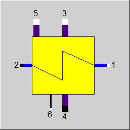
Display Option 1 |
 |
Display Option 2 |
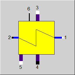 |
Display Option 3 |
Click here >> Component 107 Demo << to load an example.