EBSILON®Professional Online Documentation


|
Line connections |
|
|
|
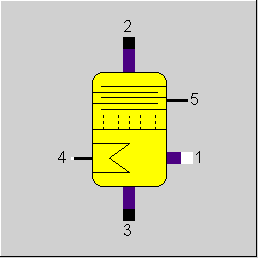
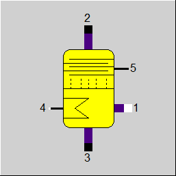
1 |
Inlet |
|
|
2 |
Steam Outlet (rich in cooling-medium) |
|
|
3 |
Fluid Outlet (poor in cooling-medium) |
|
|
4 |
Added Heat in Expeller |
|
|
5 |
Extracted Heat in Dephlegmator |
|
General User Input Values Physics Used Displays Example
This component serves to reclaim the cooling agent from the solution rich in cooling agent coming from the absorber. The solution is fed from the side. Thereby, the fluid flows down via several intermediate bottoms. This area is called the extractor. Heat is fed bottom-up and brings the fluid to the boil. Here the fact is utilized that at first mainly the cooling agent will vaporize. It will rise up and sparkle through the intermediate bottoms, whereupon an equilibrium is reached in each bottom. This way, the gaseous cooling agent accumulates to the top and the solvent accumulates downward. The area above the injection is called the dephlegmator.
The extractor temperature can be fixed in the specification value T3, but it can also be calculated using a kernel expression ET3.
Flag FT3 has to be used to set whether T3 or ET3 is to be used.
|
XI2 |
Target refrigerant content in vapour outlet |
|
EFF |
Rectifier efficiency |
|
FT3 |
Method for specification of generator outlet temperature Like in Parent Profile (Sub Profile option only) Expression =0: By specification value T3 =1: by Kernel Expression ET3 |
|
T3 |
Generator outlet temperature |
|
ET3 |
By Kernel expression ET3 function evalexpr:REAL; // result must in °C begin evalexpr:=95.0; end; |
Generally, all inputs that are visible are required. But, often default values are provided.
For more information on colour of the input fields and their descriptions see Edit Component\Specification values
For more information on design vs. off-design and nominal values see General\Accept Nominal values
|
HDPH |
(hypothetical) Dephlegmator pole (actual value) |
|
HDPHMIN |
Dephlegmator pole (theoretical minimum) |
|
HGEN |
Generator pole |
|
DHDPH |
Specific dephlegmation heat (actual value) |
|
DHDPHMIN |
Specific dephlegmation heat (theoretical minimum) |
|
DHGEN |
Specific generator heat |
|
T3MIN |
Theoretical minimum for generator temperature |
All cases |
||
|
The share of refrigerant of the liquid discharged on boiling conditions at given temperature T3: Splitting ratios: M3 - M3M1 * M1 = 0 (1) P1 - P2 = 0 (4) for FBIN = NH3/H2O: Gas emerging mixture is under saturated steam conditions for FBIN = H2O/LiBr: Outlet temperature is equal to the desorbers temperature: H3 = f(P3, T3) for FBIN = NH3/H2O: Calculation of the specific dephlegmator heat: Case 1: Entry is still sub cooled HA = H'(P1,XI1) boiling enthalpy Case 2: Entry is wet steam (2-phase mixture) T1 = f(P1,H1) temperature wet steam isotherm HDPHMIN = HA+(HB-HA)/(XIB-XIA)*(XI2-XIA) for FBIN = H2O/LiBr: H5 = DH_DPH * M2 (9) -M1*H1+M2*H2+M3*H3-M4*H4+M5*H5=0 (10) |
||
 |
Display Option 1 |
Click here >> Component 104 Demo << to load an example.