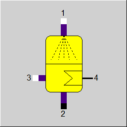

|
Line connections |
|
|
|
1 |
Fluid Inlet (lean in cooling-medium) |
|
|
2 |
Fluid Outlet (rich in cooling-medium) |
|
|
3 |
Steam Inlet (rich in cooling-medium) |
|
|
4 |
Extracted Heat |
|
General User Input Values Physics Used Displays Example
This component serves to model an absorber in an absorption refrigeration system. An ammonia / water mixture or a water / lithium bromide mixture can be used as working fluid. The gaseous cooling agent coming from the evaporator is absorbed by the solution low in cooling agent. The heat released in the process is displayed on a logic outlet.
This component includes only a global balancing of operations in the absorber. There is no difference between design and part load calculation. The exit temperature is to be specified like the component 5 (steam generators) and component 21 (firing). The amount of heat that is extracted from the liquid results from the energy balance.
|
T2 |
Outlet temperature |
Generally, all inputs that are visible are required. But, often default values are provided.
For more information on colour of the input fields and their descriptions see Edit Component\Specification values
For more information on design vs. off-design and nominal values see General\Accept Nominal values
|
RCIRC |
Circulation ratio: Ratio of the circulating liquid (line 1) to the absorbed gas (line 3) |
All Cases |
||
|
M1 + M3 - M2 = 0 M4 = 1 (Dummy value) P1 - P2 = 0 P1 - P3 = 0 P4 = 0.01 (Dummy value) H2 = f(P2,T2) M4 * H4 + M2 * H2 - M1 * H1 - M3 * H3 = 0 |
||
 |
Display Option 1 |
Click here >> Component 103 Demo << to load an example.