EBSILON®Professional Online Dokumentation


Diese Komponente ist nur noch zur Sicherstellung einer Abwärtskompatibilität mit den früheren Versionen von Ebsilon vorhanden und wird nicht mehr gepflegt. Anstelle dieser Komponente sollte in neuen Zyklen die Komponente 10 verwendet werden.
Der erforderliche Massenstrom des Heizdampfes 3 wird unter der Annahme berechnet, dass das Kondensat 4 gesättigt ist.
Die einfachste Methode, einen Wärmetauscher zu deaktivieren, ohne ihn aus dem Zyklus zu nehmen, ist die Einstellung FFU = off. Die Druckverluste werden jedoch weiterhin berücksichtigt.
Die relativen Abstrahlungsverluste können durch einen Verlustfaktor definiert werden.
|
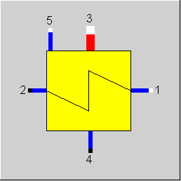
Line connections |
|
|
|
1 |
Primary inlet |
|
|
2 |
Primary outlet |
|
|
3 |
Secondary inlet |
|
|
4 |
Secondary outlet |
|
|
5 |
Secondary inlet of auxiliary condensate flow |
|
|
DTN |
Temperature input (nominal) owing to FSPEC |
|
FDP12RN |
Primary pressure loss handling Like in Parent Profile (Subprofile option only) Expression =1: calculated by DP12N= DP12RN (absolute) =2: calculated by DP12N=P1N*DP12RN (relative) |
|
DP12RN |
Pressure loss 12 (nominal) [absolute or relative to P1] |
|
FDP34RN |
Secondary pressure loss handling Like in Parent Profile (Subprofile option only) Expression =1: calculated by DP34N= DP34RN (absolute) =2: calculated by DP34N=P1N*DP34RN (relative) |
|
DP34RN |
Pressure loss 34 (nominal) [absolute or relative to P3] |
|
DQLR |
Heat loss (QL relative to Q34) |
|
FMODE |
Flag for calculation mode Design/Off-design Like in Parent Profile (Subprofile option only) Expression =0: Global =1: local off-design (immer im Teillastmodus (KAN and characteristic lines), even when a design calculation has been done globally) =2: special local off-design, calculation is analogous to off-design, but without considering the characteristic lines |
|
FFLOW |
Direction of flow Like in Parent Profile (Subprofile option only) Expression =0: countercurrent flow |
|
FSPEC |
Specifications Like in Parent Profile (Subprofile option only) Expression =0: Input DTN=DT3S2N=T3S-T2 (upper terminal temperature difference) =5: T2 given from outside (design mode only) |
|
FVOL |
Volume dependency on pressure drop Like in Parent Profile (Subprofile option only) Expression =0: without DP/DPN = (M/MN)**2 =1: with DP/DPN = V/VN*(M/MN)**2 |
|
FADAPT |
Flag for adaption polynomial ADAPT / adaptation function EADAPT Like in Parent Profile (Subprofile option only) Expression =0: =0: Not used and not evaluated =1: Correction for k*A [KA = KAN * charlines factor * polynomial] =2: Calculation of k*A [KA = KAN * polynomial] =1000: Not used but ADAPT evaluated as RADAPT (Reduction of the computing time)
=-2: Calculation of k*A [KA = KAN * adaptation function] =-1000: Not used but EADAPT evaluated as RADAPT (Reduction of the computing time)
|
|
EADAPT |
Adaptation function |
|
FFU |
On-/Off switch
Like in Parent Profile (Subprofile option only) Expression =0: Heat-exchanger inactive =1: Heat-exchanger active |
|
KAN |
K*A (nominal) |
|
M1N |
Primary mass flow (nominal) |
|
M3N |
Secondary mass flow (nominal) |
|
QN |
Heat-exchanger power (nominal)=Q34N |
|
V1N |
Specific volume for primary side inlet 1 (nominal) |
|
V3N |
Specific volume for secondary side inlet 3 (nominal) |
The parameters marked in blue are reference quantities for the off-design mode. The actual off-design values refer to these quantities in the equations used.
Generally, all inputs that are visible are required. But, often default values are provided.
For more information on color of the input fields and their descriptions see Edit Component\Specification values
For more information on design vs. off-design and nominal values see General\Accept Nominal values
The following table shows, whether KAN or DTN is to be used, or whether T2 or M2 are to be calculated or specified as defaults respectively:
|
|
GLOBAL = Design |
GLOBAL = Off-design |
||
|
|
FMODE = Design |
FMODE = Off-design (local) =1,2 |
FMODE = Design |
FMODE = Off-design (local) =1,2 |
|
KAN |
Value optional |
specified by the user |
specified by the user |
specified by the user |
|
DTN |
Value optional |
Value optional |
Value optional |
Value optional |
1. Characteristic line FK1 = f (M1/M1N)
2. Characteristic line FK2 = f (M3/M3N)
(k*A) / (k*A)N = FK1 * FK2
|
Characteristic line 1: (k*A)-characteristic line: (k*A)1/(k*A)N = f (M1/M1N) |
|
X-axis 1 M1/M1N 1. point |
|
Characteristic line 2: (k*A)-characteristic line : (k*A)2/(k*A)N = f (M3/M3N) |
|
X-axis 1 M3/M3N 1. point |
|
Allcases |
||
|
|
if FDP12RN=relative, then {DP12N=P1*DP12RN} else {DP12N=DP12RN} if FDP34RN=relative, then {DP34N=P3*DP34RN} else {DP34N=DP34RN} |
|
|
Design case (Simulation flag: GLOBAL = design case AND FMODE = design case) |
||
|
|
T3S = f'(P3) P2 = P1 - DP12N (1) if upper terminal temperature difference is given by FSPEC, then { T2 = T3S DTN }
if T2 is given by FSPEC, then { T2 = DTN }
H2 = f(P2,T2) M2 = M1 (7) Q2 = M2 * H2 DQ = M2 * H2 - M1 * H1 (5)
P4 = P3 - DP34N (2) P5 = P4 (3)
H4S=f(P4) M3 = (DQ/(1-DQLR) - M5 * (H5 - H4S))/(H3 - H4S) (6) Q4 = Q3 + Q5 - DQ/(1-DQLR) M4 = M3 + M5 (8) H4S = Q4/M4 (4) T4 = f(P4)
DTLO = T4 - T1 (for FFLOW = countercurrent) DTUP = T3 - T2 (for FFLOW = countercurrent)
LMTD = (DTUP - DTLO)/(ln(DTUP) - ln(DTLO)) KAN = DQ/LMTD |
|
|
Off-design case (Simulation flag: GLOBAL = off-design or FMODE = off-design) |
||
|
|
F1 = (M1/M1N) ** 2 for GLOBAL = design, F1= 1.0
P2 = P1 - DP12N * F1 (1)
F3 = (M3/M3N) ** 2 for GLOBAL = design, F3= 1.0
P4 = P3 - DP34N * F3 (2)
M2 = M1 (7) if GLOBAL = design { Fk1 = 1.0 Fk2 = 1.0 }
if GLOBAL = off-design { Fk1 = f (M1/M1N) from characteristic line 1 Fk2 = f (M3/M3N) from characteristic line 2 }
KA = KAN * Fk1 * Fk2
P4 = P5 (3) M4 = M3 + M5 (8)
Maximum/minimum values for the iteration { T4=f(P4) (4) H4S=f(P4) H2max = f(P2,T3) Q21max = M1 * (H2max - H1) Q34max = Q3 + Q5 M4*H4S
Qmax = min(Q21max,Q34max) Q21 = 0.5*Qmax
Iteration { H2 = H1 + Q21/M2 T2 = f(P2,H2)
DTLO = T4 - T1 (for FFLOW = countercurrent) DTUP = T3 - T2 (for FFLOW = countercurrent)
LMTD = (DTUP - DTLO)/(ln(DTUP) - ln(DTLO))
QQ = KA * LMTD DQQ_1 = DQQ DQQ = Q21 - QQ
regula - falsi method { Size = (Q21 - Q21_1)/(DQQ - DQQ_1) for iteration step 1: Size of the last global step Q21X = Q21 - DQQ * Size Q21_1 = Q21 Q21 = Q21X }
DQ = |DQQ /((Q21+QQ)*.5)| if DQ < TOL, then end the iteration else continue the iteration }
M3 = (Q21/(1-DQLR) - M5 * (H5 - H4S))/(H3 - H4S) (6) Q4 = M4 * H4S Q21 = (Q3 + Q5 - Q4) * (1-DQLR) Q2 = Q1 + Q21 H2 = Q2 / M2 T2 = f (P2,H2) DQ = M2 * H2 - M1 * H1 (5)
|
|
|
Eq. No. |
|
Line |
||||
|
|
|
1 |
2 |
3 |
4 |
5 |
|
1 |
P |
X |
X |
|
|
|
|
2 |
P |
|
|
X |
X |
|
|
3 |
P |
|
|
X |
|
X |
|
4 |
H |
|
|
|
(X) |
|
|
5 |
H |
X |
X |
|
|
|
|
5 |
M |
X |
X |
|
|
|
|
6 |
H |
X |
X |
X |
X |
X |
|
6 |
M |
X |
X |
(X) |
X |
X |
|
7 |
M |
X |
X |
|
|
|
|
8 |
M |
|
|
X |
X |
X |
Click here >> Component 66 Demo << to load an example.