
EBSILON®Professional Online Dokumentation


|
Anschlüsse |
|
|
|
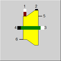
1 |
Fluid-Eintritt |
|
|
2 |
Fluid-Austritt |
|
|
3 |
Welleneintritt |
|
|
4 |
Wellenaustritt |
|
|
5 |
Regeleingang |
|
|
6 |
Regeleingang für Wirkungsgrad (als Enthalpie) |
|
Alllgemeines Vorgabewerte Kennfelder Physik Ansichten Beispiel
Die Komponente 164 stellt eine kennfeldbasierte Turbine dar, die das Verhalten von Durchflussmenge, Druckabfall und Drehzahl modelliert. Die Komponente versucht, die Kennfelder des Herstellers direkt zu verwenden, ohne dass der Benutzer sie manuell umwandeln muss. Die Kennfelder können über ein Importwerkzeug importiert werden, das die manuelle Umwandlung eines Turbinenkartenbildes in eine Turbinenkartentabelle ermöglicht.
Ein Turbinenkennfeld wird durch (X,Y,Z,EFF) Datenpunkte mit verschiedenen Optionen für X,Y,Z,EFF dargestellt. Die Berechnungsmodi ermöglichen die Berechnung eines beliebigen X,Y,Z-Punktes aus den beiden anderen.
Um den korrekten dimensionslosen reduzierten Durchfluss und die reduzierte Geschwindigkeit abzuleiten, ist es notwendig, die korrekten Bezugseigenschaften MW_REF, T_REF, P_REF, Z_REF, K_REF einzustellen, falls sie in den Einstellungen verwendet werden.
Wenn das Kennfeld in Form von Machzahlen angegeben wird, müssen die Maße DIN und DIMP eingestellt werden, um die tatsächlichen Machzahlen berechnen zu können.
Wenn der Wirkungsgrad und der Druckabfall in Form von Gesamtwerten und statischen Werten angegeben werden, muss der Auslassdurchmesser DOUT eingestellt werden, um zwischen Gesamtwerten und statischen Werten umrechnen zu können.
Wenn Leistungsfaktoren aktiviert sind, werden die folgenden Beziehungen verwendet:
| EFF = | EFF_aus_Kennfeld_gelesen * PFEFF | (FCALC=1,2,3) |
| X = | X_aus_Kennfeld_gelesen * PFX | (FCALC=2) |
| Z = | Z_aus_Kennfeld_gelesen * PFZ | (FCALC=1) |
| X_zum_Kennfeldlesen_genutzt = | X / PFX | (FCALC=1,3) |
| Z_zum_Kennfeldlesen_genutzt = | Z / PFZ | (FCALC=2,3) |
|
FCALC |
Berechnungsmethode: =0: Bypass (Ausgane = Eingang) =1: berechne Z(X,Y) =2: berechne X(Y,Z) =3: berechne Y(X,Z) |
|
MW_REF |
Referenz-Molekulargewicht des Kennfelds |
|
T_REF |
Kennfeld-Referenz-Eintrittstemperatu |
|
P_REF |
Referenz-Eintrittsdruck des Kennfelds |
|
Z_REF |
Eintritts-Referenz-Kompressibilitätsfaktor Zref = Pref*Vref/(R*Tref) |
|
K_REF |
Eintritts-Referenz-Isentropenexponent (k=cp/cv) |
|
DIN |
Eintrittsdurchmesser |
|
DOUT |
Austrittsdurchmesser |
|
DIMP |
Durchmesser der Laufradschaufelspitze |
|
N_REF |
Referenz korrigierte Drehzahl |
|
FX |
Flag Z_REF in FX and FY verwenden: =0: X ist korrigierter Durchsatz (M1*SQRT((T1/T1ref)*(MWref/MW)/(P1/P1ref))) =1: X ist axiale Machzahl =2: X ist Volumenstrom =3: X ist Fluss-Parameter (M1*SQRT(T1/P1*(MWref/MW))) |
|
FY |
Flag für Y Definition: =0: Y ist Korrigierte Drehzahl =1: Y ist Rotations-Machzahl =2: Y ist relative Korrigierte Drehzahl =3: Y ist Drehzahl-Parameter (RPM*SQRT(T1*(MWref/MW))) |
|
FZ |
Flag für Z Definition: =0: Z ist Druckverhältnis =1: Z ist isentrope Förderhöhe =2: Z ist Austrittsdruck (Druckverhältnis PR=Pout/P_REF) |
|
FEFF |
Flag für Wirkungsgradeingang (Kennfeld MXCMAP, Spalte 4): =0: setze Wirkungsgrad =1: setze Leistungsverbrauch |
|
FPREFF |
Flag für PR und EFF Definition: =0: PR and EFF sind total zu statisch =1: PR and EFF sind total zu total |
|
EFFM |
Mechanischer Wirkungsgrad |
|
FMAPGROUP |
Turbinen-Kennfeldap Gruppenparameter: =0: Y (Kurven bei konstantem Drehzahlparameter) =1: X (Kurven bei konstantem Fluss-Parameter) =2: Z (Kurven bei konstantem Druck-Parameter) |
|
LOSSM |
Mechanischer Verlust (konstanter Anteil) |
|
FPFEFF |
Flag für Gütegrad Wirkungsgrad-Einstellungen: =0: Nichts =1: Wert PFEFF verwenden =2: Ausdruck EP FEFF verwenden =3: Matrix MXPFEFF verwenden |
|
PFEFF |
Gütegrad Wirkungsgrad |
|
EPFEFF |
Ausdruck für Gütegrad Wirkungsgrad |
|
FPFX |
Flag für Gütegrad X Einstellungen (gegenseitig ausschließend zu FPFZ): =0: Nichts =1: Wert PFX verwenden =2: Ausdruck EPFX verwenden =3: Matrix MXPFX verwenden |
|
PFX |
Gütegrad X |
|
EPFX |
Ausdruck für Gütegrad X |
|
FPFZ |
Flag für Gütegrad Z Einstellungen (gegenseitig ausschließend zu FPFX): =0: Nichts =1: Wert PFZ verwenden =2: Ausdruck EPFZ verwenden =3: Matrix MXPFZ verwenden |
|
PFZ |
Gütegrad Z |
|
EPFZ |
Ausdruck für Gütegrad Z |
Die blau markierten Parameter sind Bezugsgrößen für den Off-Design-Modus. Diese werden bei der Auslegungsberechnung von EBSILON®Professional errechnet und eingetragen.
Im Allgemeinen sind alle sichtbaren Eingaben erforderlich. Häufig werden jedoch Standardwerte angegeben.
Weitere Informationen zur Farbe der Eingabefelder und deren Beschreibungen finden Sie unter Komponenten bearbeiten\Vorgabewerte.
Weitere Informationen zu Auslegungs- vs. Nicht-Auslegungs- und Nennwerten finden Sie unter Allgemeine Einstellungen\Nominalwerte übernehmen.
|
MXTMAP |
Spalte 1 =Y |
Spalte 2=X |
Spalte 3=Z |
Spalte 4 =EFF oder PWR |
Kern-Turbinenkennfeld |
|
MXSURGE |
Spalte 1 =X |
Spalte 2=Z |
? |
||
|
MXEFFISO |
Spalte 1 =ID |
Spalte 2=X |
Spalte 3=Z |
Spalte 4 =EFF |
Wirkungsgrad-Isolinien-Daten. Wird nicht in Berechnungen verwendet, sondern nur im Importer-Tool |
|
MXPFEFF |
Spalte 1 =Y |
Spalte 2=X |
Spalte 3=PFEFF |
Gütgrad-Korrektur EFF ( X, y, cfEFF ) |
|
|
MXPFX |
Spalte 1 =Y |
Spalte 2=Z |
Spalte 3=PFX |
Gütgrad-Korrektur X ( Y,Z,cfX ) |
|
|
MXPFZ |
Spalte 1 =Y |
Spalte 2=X |
Spalte 3=PFZ |
Gütgrad-Korrektur Z ( Y,X,cfZ ) |
|
Q |
Shaft power |
|
RFLOW |
Korrigierter Fluss (Durchsatz) |
|
RSPEED |
Korrigierte Drehzahl |
|
RELRSPEED |
Relative korrigierte Drehzahl |
|
RFLOWPAR |
Reduzierter Fluss Parameter |
|
RSPEEDPAR |
Reduzierte Drehzahl Parameter |
|
FLOW |
Durchsatz |
|
SPEED |
Wellendrehzahl |
|
PR_TT |
Druckverhältnis total-total |
|
PR_TS |
Druckverhältnis total-statisch |
|
P1_T |
Eintrittsdruck total |
|
P1_S |
Eintrittsdruck statisch |
|
P2_T |
Entladedruck total |
|
P2_S |
Entladedruck statisch |
|
MCH_AX |
Mach-Zahl exial |
|
MCH_RAD |
Mach-Zahl radial |
|
RIGV |
? |
|
EFFI_TT |
Wirkungsgrad isentrop total-total |
|
EFFI_TS |
Wirkungsgrad isentrop total-statisch |
|
EFFP_TT |
Wirkungsgrad polytrop total-total Verwendeter Wert des Anpassungspolynoms |
|
HDISEN_TT |
Isentrope Förderhöhe total-total |
|
HDISEN_TS |
Isentrope Förderhöhe total-statisch |
|
VM1 |
Eintritts-Volumenstrom |
|
RPFEFF |
Gütegrad Wirkungsgrad |
|
RPFX |
Gütegrad X |
|
RPFZ |
Gütegrad Z |
|
FCALC = 0 |
Bypass (Ausgang = Eingang) |
|
FCALC = 1 |
Berechne Z(X,Y) |
|
FCALC = 2 |
Berechne X(Y,Z) |
|
FCALC = 3 |
Berechne Y(X,Z) |
|
M2 - M1 = 0 |
|
|
M4 - M3 = 0 |
|
|
H2 - H1 = dH |
|
|
H4 - H3 = -M1 * dH * EFFM - LOSSM |
|
|
P2 - Druckverhältnis * P1 = 0 (FCALC = 1) M1 = Eintrittsmassenstrom (FCALC = 2) M3 = RPM (FCALC = 3) |
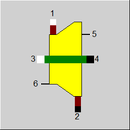 |
Ansicht 1: Turbine |
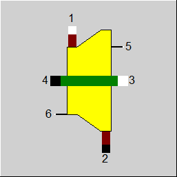 |
Ansicht 2: Turbine |
 |
Ansicht 3: Turbine |
 |
Ansicht 4: Turbine |
Hier klicken >> Component 164 Demo << um ein Beispielmodell zu laden.