
EBSILON®Professional offers two types of reports in text format (ASCII):
The report "Validation results" is available as Excel file as well.
In addition, it is possible to create an Excel bar diagram that displays differences between validated and measured values.
The layout of the text reports was retained from ancient Ebsilon versions because some users may have written programs for a further evaluation that require that format. If you do not like it, use the Excel version or create your own-style reports either by the User Excel or the User DLL interface. If you need a text file, you can convert it within Excel.
These reports always refer to the actual profile. This is the profile that is currently active on the screen. That can be different from the last calculated profile.
To create this report, use the menu command "DataàMeasured ValuesàReportàValidation Results (ASCII)". The report will be created in the same directory as your original file, with the name
“model_results.val”,
where “model” is replaced by the actual name of your EBSILON®Professional model. If this file already existed, it will be overwritten without notice (this behaviour is identical to ancient Ebsilon versions). If you want to save your report, copy or rename it before you create the next report.
There is a setting that this report will be generated automatically after each calculation (simulation or validation). This setting can be activated on "ExtrasàGeneral Options", tab "Calculation". Activate the checkbox "Report results of validation to val-file".
If you perform the calculation within an EbsScript, the report is not updated automatically, because it would be difficult to access it before it would be overwritten by the next calculation.
Note that this report can be used to display the results of a validation or a simulation. It depends on the type of calculation that you performed last for the actual profile.
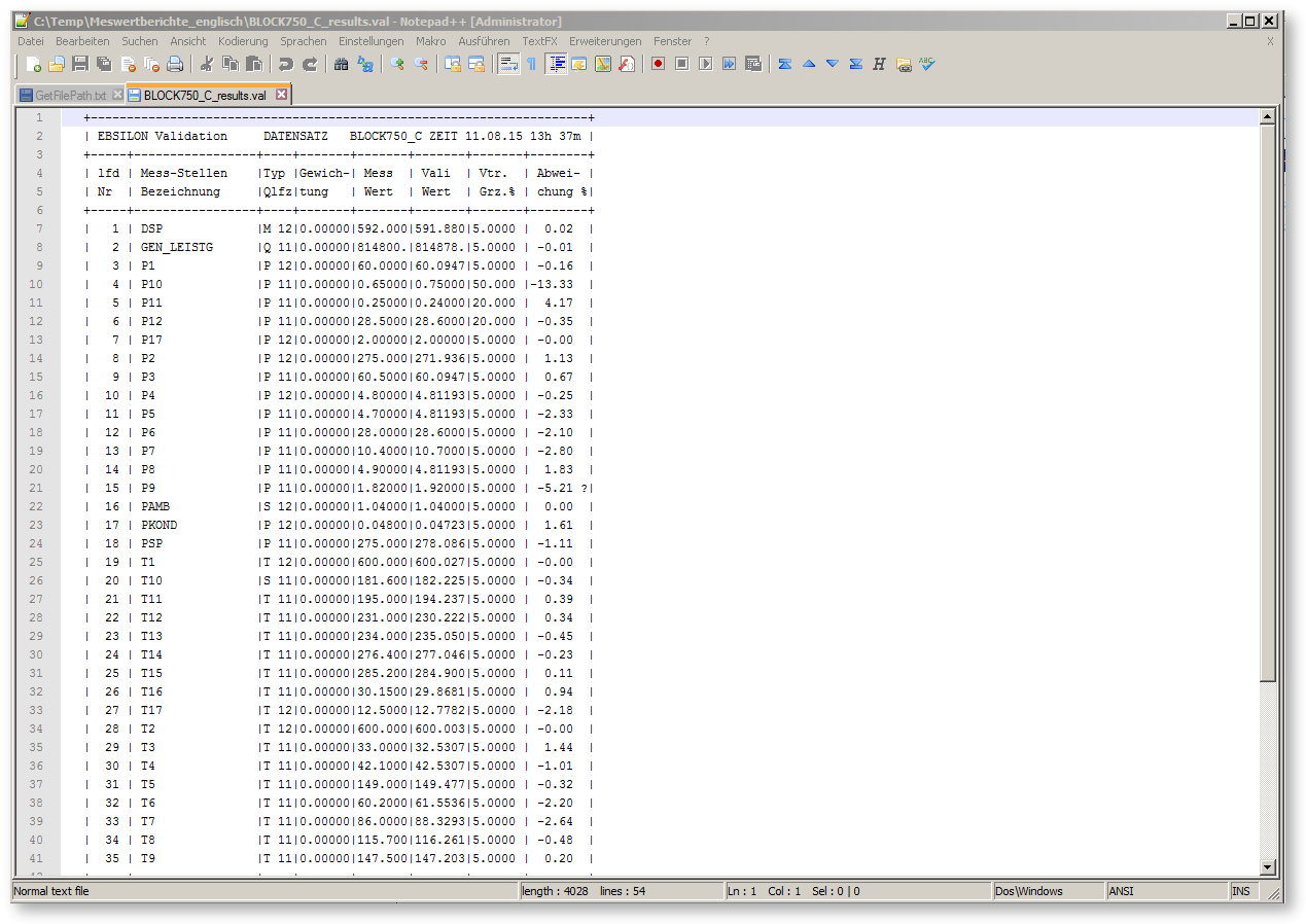
The report will look like this (it is really in German as it was in earlier Ebsilon versions):

The header line displays the type of calculation (simulation or validation), the model name and the current time.
The table contains a listing of all measured values (component 46) in the model, one row for each measured value. The columns in the table display
o P = Pressure,
o T = Temperature,
o H = Enthalpy,
o M = Mass flow,
o Q = Energy or Heat flow,
o S for all others,
followed by a number that indicates the usage of that measurement point:
o 0 if the measurement point is not used at all (switched off),
o 11 if the measurement point is used in validation only (redundant point),
o 12 if the measurement point is used in simulation and validation.
Important: This report always uses the SI unit system with "bar", "°C", "kg/s", "kW", "kJ/kg", independent from the unit system selected on your screen or used by the single components. If you prefer other units, use the Excel version of this report.
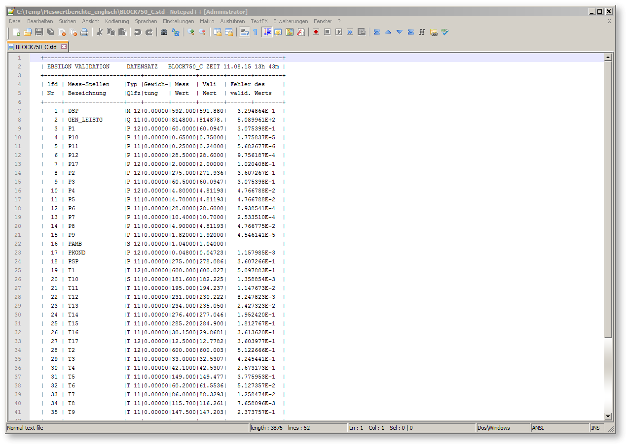
This is a special report that displays statistical properties for the validation. The “deviation” in this report is an indication of the reliability of the validated value by itself, depending on the weight and on the redundancy in the system. It is not the relative deviation of the measured from the validated value.
Example: In the listing, for P10 there is a measured value 0.65 bar, while the validated value is 0.75035. The relative deviation of the measured value–13.37 % (see the table above in the last chapter). That means that the measured value is 13.37 % smaller than the validated value. In the table below, an expected error of 3.39*10^-7 is displayed. That means, that due to the statistics of the calculation, you can expect that the "true" value does differ more than 3.39*10^-7 from the calculated validated value.
Usually, you do not need this report. It just tells you whether you redundancy is high enough to neglect statistical errors.
If you want to create the report, you have to
The reports looks similar to the “validation results” report. Actually, only the last column is different. It contains the expected error of the validated value.

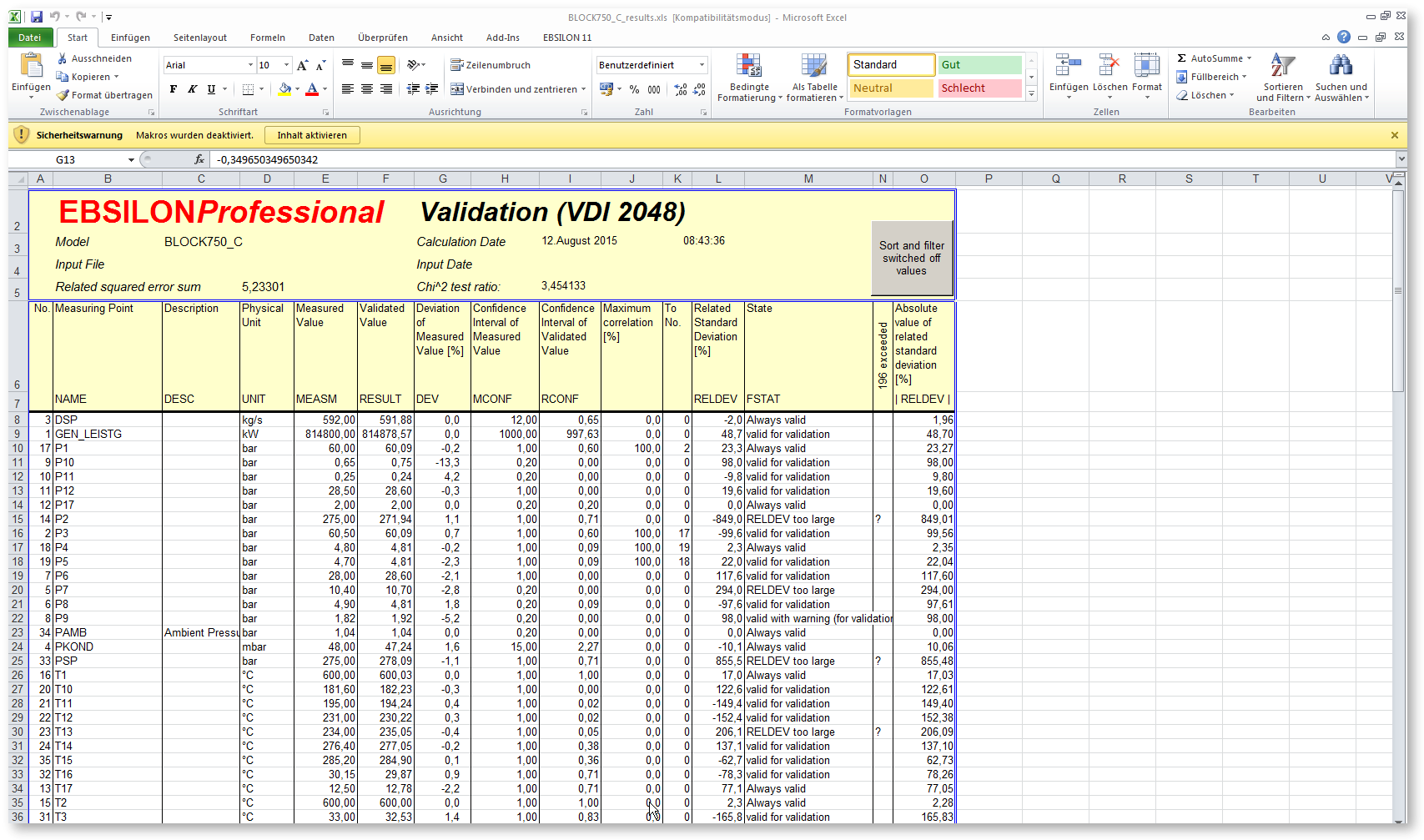
For your convenience, the menu command "DataàMeasured ValuesàReportàValidation Results (Excel)" allows to create an Excel sheet that contains the same information like the corresponding ASCII report (of course you could create such a report by yourself using a User Excel (template).
Like for the ASCII report, you can activate an automatic creation of that report. This setting can be activated on "ExtrasàGeneral Options", tab "Calculation" with the checkbox "Report results of validation to Excel-file".
The Excel file will be created in the same directory as your original file, with the name
"model_results.xls",
where "model" is replaced by the actual name of your EBSILON®Professional. If this file already existed, it will be overwritten without notice.

Unlike the ASCII report, the Excel report is available in English and in German, depending on the set of Excel templates that you selected in "ExtrasàGeneral OptionsàPaths", entry "Path to Excel Workbook Templates". Specify the sub-directory "data\exceltempl\EN" for English and "data\exceltempl\GE" for German. This is not switched automatically when you switch the language, because you may specify different paths here if you want to use own templates.
An important advantage of the Excel version of this report is the flexibility in the unit system. The Excel report uses the units that are displayed on the screen, and the unit is reported in the column "Physical Unit". In the listing above, you see that POND is displayed in "mbar" while other pressures are expressed in "bar". This was achieved by using the setting "From spec. value/result" for the Unit System on "ExtrasàGeneral Options", sheet "View & Print".
For the meaning of the other columns, see the description of the ASCII Report.
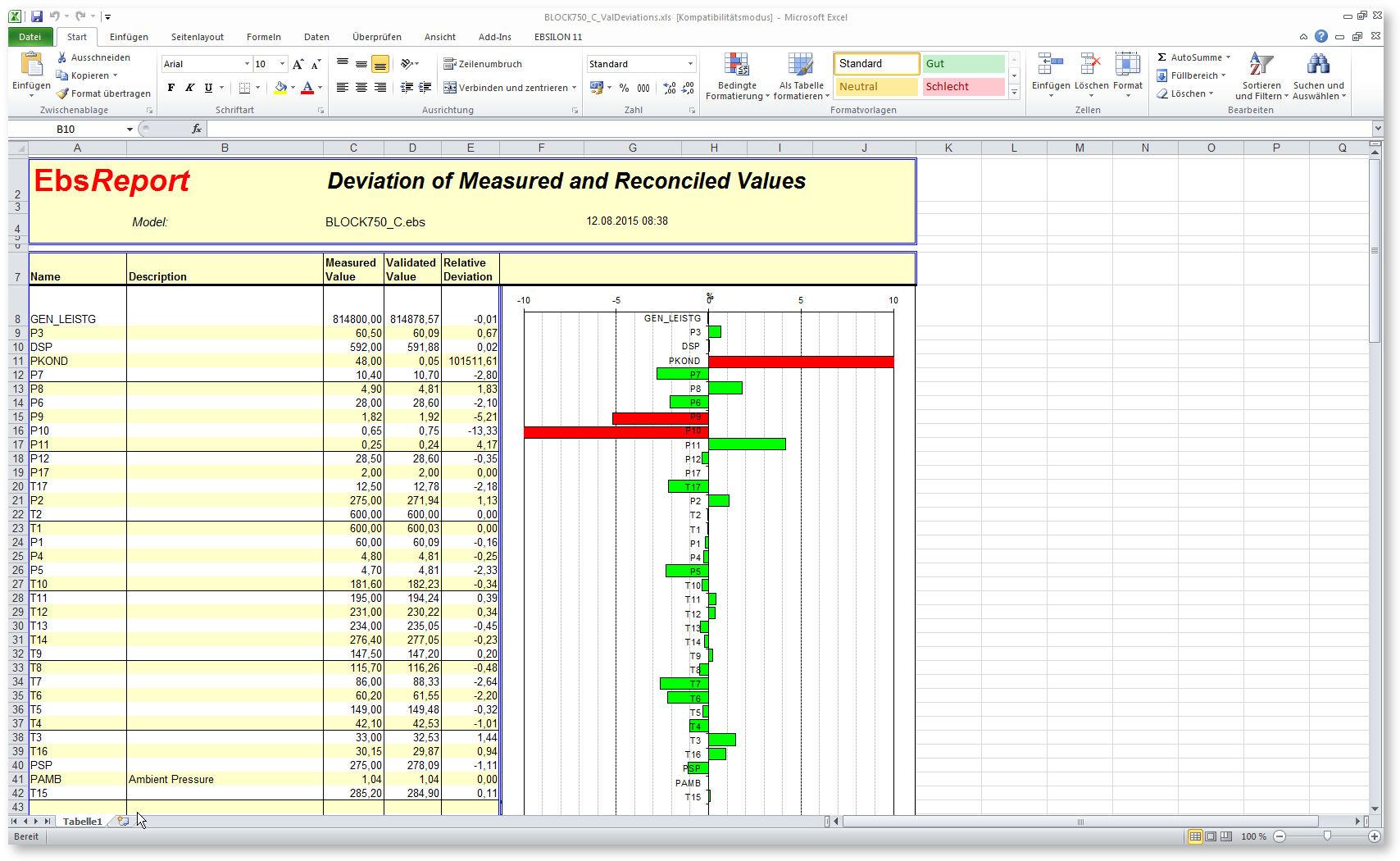
If you prefer a graphical presentation of the deviations between measured and validated values, you can use the menu command "DataàMeasured ValuesàReportàValidation Diagram".
This feature actually creates an User Excel Report using the template "TemplateValDeviations.xls".

The report includes file name and creation time, and for each measured value
and a bar diagram that graphically displays this deviations (up to 10 % in each direction). Red bars indicate that the relative deviations exceeds 5 %.