EBSILON®Professional Online Documentation


|
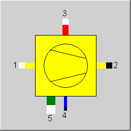
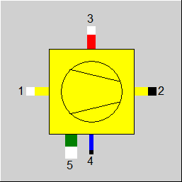
Line connections |
|
|
|
1 |
Air inlet |
|
|
2 |
Air outlet |
|
|
3 |
Steam inlet |
|
|
4 |
Condensate outlet |
|
|
5 |
Fan power |
|
General User Input Values Characteristic Lines Physics Used Displays Example
Component 75 represents an air-cooled condenser (ACC). A polynomial describes the condenser performance in terms of condensing pressure as a function of ambient temperature and condenser load. The polynomial has the form:
ln(pcond)=A1 + A2 * TAir*CQ + A3*CQ + A4*TAir + B1*TAir² + B2*CQ² + B3* TAir*CQ² + B4* TAir²*CQ
With
TAir [°K] Air inlet temperature
CQ [-] Load ratio in terms of Duty/Duty (@100% Load)
pcond [bar] Steam turbine back-pressure.
As such component 75 can be used to model a specific design and vendor data are required to determine the coefficients A1-A4 and B1 - B4. It is important to determine the coefficients using above variables in the given set of units of measure.
Typically air-cooled condensers come in arrays of A-Frame Cells with a fan diameter of about 10 m (33Ft) and multiple cells per array. Regardless of the total size (duty) of the air-cooled condenser, the size of one cell remains constant, the adaption to various duties is accomplished by the number of cells employed. The variation of one cell between different designs relates to the tube arrangement, tube sizing and fins, and design air flow, which unfortunately results in different component behaviour over the anticipated load range. That is why it is important to use vendor data for a specifically tuned ACC model.
An array of multiple cells could be modelled, using the components 75 for one cell and Mass Multiplier as shown in the following figures:
One A-Frame type cell
Ebsilon model to simulate an array of cells
Table 1 shows input values for 2 typical designs, which can safely be adopted to represent as build ACC. Design 1 is characterized by a high unit loading with one unit operating in an array of 5 cells, the whole unit operating at high ambient temperatures. Design 2 shows a unit operating in an array of 60 cells hence a comparatively large total ACC size. One cell is characterized by medium loading, with smaller air flow, operating in a moderate climate.
|
Rating per Cell |
|
|
Design 1 |
Design 2 |
|
Dry Steam Flow |
M3 |
kg/s |
5.850 |
3.663 |
|
ST back-pressure |
P3 |
bar |
0.257 |
0.060 |
|
Duty |
QNULL |
kW |
13714.2 |
8182.2 |
|
Air Temperature |
TFAG |
°C |
39 |
15 |
|
Fan Shaft Power |
PFAG |
kW |
115 |
57.67 |
|
Motor Rating |
|
kW |
150 |
75 |
|
Speed |
|
|
1 |
1 |
|
Ambient Pressure |
|
bar |
1.013 |
0.977 |
|
Air Flow |
|
m³/s |
621.5 |
470.0 |
|
Validity Range |
|
°C / °C |
3/50 |
10/40 |
|
Coefficients |
A1 |
- |
-10.5383 |
-20.52267 |
|
|
A2 |
- |
-0.035522 |
-0.072951 |
|
|
A3 |
- |
7.7276076 |
14.288614 |
|
|
A4 |
- |
0 |
0.0573392 |
|
|
B1 |
- |
8.10E-05 |
0 |
|
|
B2 |
- |
-0.888411 |
-1.459208 |
|
|
B3 |
- |
0.002581 |
0.0044909 |
|
|
B4 |
- |
4.8478E-05 |
9.7380E-05 |
Design #1 agreement of model results vs. vendor data
Design #2 agreement of model vs. vendor data
|
DTUK |
Degrees of sub cooling |
|
QNUL |
Heat released at 100% load |
|
PFAG |
Fan power at 100% |
|
TFAG |
Air temperature at 100% load |
|
FCHR |
P3 calculation Expression =0: use of polynomial (ADAPT) for ln(P3) =1: P3 given (polynomial not used) |
|
FADAPT |
Flag for using the adaptation polynomial ADAPT/ adaptation function EADAPT Like in Parent Profile (Sub Profile option only) Expression =0: Not used and not evaluated =1: Correction for P3 [P3 = (polynomial with A1..B4) * (user defined polynomial ADAPT) ] =2: Calculation of P3 [P3 = user defined polynomial ADAPT ] =1000: Not used, but ADAPT evaluated as RADAPT (Reduction of the computing time) = -1: Correction for P3 [P3 = (polynomial with A1..B4) * (user defined adaptation function) ] = -2: Calculation of P3 [P3 = user defined adaptation function] = -1000: Not used, but EADAPT evaluated as RADAPT (Reduction of the computing time) |
|
EADAPT |
Adaptation function |
|
A1 |
Coefficient for characteristic field (see section on characteristic field) |
|
A2 |
Coefficient for characteristic field (see section on characteristic field) |
|
A3 |
Coefficient for characteristic field (see section on characteristic field) |
|
A4 |
Coefficient for characteristic field (see section on characteristic field) |
|
B1 |
Coefficient for characteristic field (see section on characteristic field) |
|
B2 |
Coefficient for characteristic field (see section on characteristic field) |
|
B3 |
Coefficient for characteristic field (see section on characteristic field) |
|
B4 |
Coefficient for characteristic field (see section on characteristic field) |
P3 =EXP[ A1 + A2*(T1K*CQ) + A3*CQ + A4*T1K +B1*T1K**2 + B2*CQ**2 + B3*(T1K*CQ**2)+B4*(T1K**2*CQ) ]
|
All cases |
||
|
|
M2 = M1 M4 = M3 P2 = P1 CQ = M3*(H3-H4) / QNUL T1K=T1+273.15 , T1K [Kelvin] P3 =EXP[ A1 + A2*(T1K*CQ) + A3*CQ + A4*T1K +B1*T1K**2 + B2*CQ**2 + B3*(T1K*CQ**2) +B4*(T1K**2*CQ) ]
P4 = P3 T4 = Tsat(P3) - DTUK M1*(H2-H1) = M3*(H3-H4)
calculated fan power: Q5 = T1/TFAG * PFAG [Check Unit of T] |
|
 |
Display Option 1 |
Click here >> Component 75 Demo << to load an example.