EBSILON®Professional Online Documentation
In This Topic
    Component 143: Wind Turbine
    In This Topic

    Component 143: wind turbine


    Specifications

    Line connections

    1

    Power outlet


    General       User Input Values       Results       Displays       Example


    General 

    Component 143 represents a wind turbine. Based on the power curve provided by the manufacturer of the wind turbine, the generated electrical output is determined depending on the mean wind speed at hub height.

    The relation between the power output P of a wind turbine, the undisturbed wind speed v1 at hub height, and the power coefficient cP is as follows:

    Here applies: R – rotor radius, ρ – air density.
    The power coefficient cP is a measure of the aerodynamic efficiency of the wind turbine. The higher the value of cP the higher the portion of the wind kinetic energy converted to the power output. The typical values of cP can reach for modern wind turbine airfoil profiles up to 0.5 at optimal conditions (no blade pitching).
    Depending on whether the wind turbine is in the planning stage or already in operation and equipped with measurements, the wind speed at hub height can be used either from the result of the calculation of the values from Component 142 (Wind data) or as a direct specification value in Component 143. Various algorithms are used in the case of a calculation of the wind speed from Component 142 to the actual hub height (cf. the specification of Component 142).
    As the power characteristic of the manufacturer refers to the wind speed normalized according to IEC 61400-12-1, it is necessary to know the current air temperature and the air pressure to convert the current wind speed to the wind speed at the ISO reference density of 1.225 kg/m³. The values for the current air temperature and the air pressure are the same for all wind turbines of the wind farm and are therefore specified in one Component 142.
    Also, when the individual wind turbines of a wind farm are located too close to each other, a wake flow generated by a wind turbine may influence another wind turbine, depending on the wind direction. Also the orology of the location (the surface irregularities of the area) has an influence on the spatial wind distribution. For instance, the wind turbines of a wind farm that are installed at different ground levels may be exposed to different wind speeds. For such effects, a power correction factor FW is provided in Component 143, which depends on two parameters in a specification value matrix, the undisturbed wind speed and the wind direction. FW=1 means no correction, i.e. the wind turbine converts the undisturbed wind speed at hub height into the electrical output precisely according to the specified power characteristic. With values FW<1 e.g. the wake flow effects due to other wind turbines can be represented. Values FW>1 are conceivable as well if e.g. the airflow is accelerated by a rise of ground.

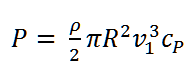
    Specification of voltage, frequency and type of current in the component:

    It is possible to specify the voltage (VOLT), frequency (FREQ) and type of current  (NPHAS) as the default value in the component.    

    The flags FVOLT and FFREQ are used to set whether the specification is to be made by the new specification values VOLT and FREQ respectively (0) or externally as a measured values on the electrical line (-1).


    Warning!: A warning will be output if the minimum hub height is fallen below.

    Default value database

    Data from various manufacturers have been stored in the default value database for this component.


    User Input Values

    TYPENAME

    Wind turbine type name

    FFU

    Turbine switched
    Like in Parent Profile (Sub profile option only)
    Expression

    =0: OFF

    =1: ON

    IWDATA 

    Index for comp.142, to use wind parameters

    FIDENT

    Calculation mode

    Like in Parent Profile (Sub profile option only)
    Expression

    =0: Simulation - wind speed given, output power computed ,using power curve

    =1: Identification - wind speed and output power given, power coefficient computed

    ROTDIAM

    Rotor diameter

    HH

    Hub height


    HHMIN

    Minimum hub height

    Z0

    Roughness length

    FVWHH

    Handling of the wind speed at hub height

    Like in Parent Profile (Sub profile option only)
    Expression

    =0: use directly the value of VWHH

    =1: recompute the value of VWIND from comp. 142 to the hub height using logarithmic vertical velocity profile ( Algorithm 1 of comp. 142)

    =2: recompute the value of VWIND from comp. 142 to the hub height using logarithmic vertical velocity profile and Monin-Obukhov length acc. to TA Luft, VDI 3783-8 Bl. 1 and VDI 3783 Bl. 8 ( Algorithm 2 of comp. 142)

    VWHH

    Wind speed at hub height

    FFW

    Use power correction factor FW

    Like in Parent Profile (Sub profile option only)
    Expression

    =0: OFF

    =1: ON

    FVOLT

    Flag for  the method for specification of voltage

    Like in Parent Profile (Sub profile option only)

    Expression

    =0: Defined by specification value VOLT

    =-1: Voltage given externally on electrical outlet

    VOLT

    Voltage (on electric lines)

    FFREQ

    Flag for  the method for specification of frequency   

    Like in Parent Profile (Sub profile option only)

    Expression

    =0: Use specification value FREQ

    =-1: Frequency given externally on electrical outlet

    FREQ

    Generator frequency

    NPHAS

    Type of current                

    Like in Parent Profile (Sub profile option only)

    Expression

    =0: Direct current

    =1: One-phase alternating current
    =3: Three-phase alternating current


    Result Values

    AS

    Swept area

    RVWHH 

    Computed wind speed at hub height without normalization acc. to IEC-61400-12-1

    RVWHHIEC

    Computed wind speed at hub height normalized acc. to IEC 61400-12-1

    CP

    Overall power coefficient

    Characteristic line

    Char.line 1: Power produced  Q1 = f (VWHHIEC) (Wind speed at hub height normalized acc. to IEC)

         X-Axis           1         VWHHIEC            1. Point
                              2         VWHHIEC            2. Point
                              .
                             N         VWHHIEC             last Point
     
         Y-Axis          1          Q1                    1. Point
                             2          Q1                    2. Point
                             .
                             N         Q1                    last Point


    Input matrix

    MXFW :     Power correction factor FW depending on the wind speed at hub height normalized acc. to IEC 61400-12-1 and wind direction


    Component displays

    Display option 1

    Example

    Click here >> Component 143 Demo << to load an example.