
New preheater model
1. Problem description and motivation
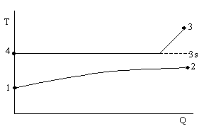
The classical method used for calculation of component 10 (FRABEK =0) assumes that the influence of superheated steam on the heat transfer can be ignored.

Fig 1: Q-T-Diagram (classical method)
1: inlet water
2: outlet water
3: inlet steam
4: outlet condensate
3s: saturation temperature of the pressure P3
All relations use temperature T3s. for the calculation of temperature differences.
The following disadvantages occur from this:
2. Suggested solution
To solve this problem basically a partitioning of heating surface into desuperheating and condensation area is necessary, which can be shifted in case of part load. In (G. Rabek: Die Ermittlung der Betriebsverhältnisse von Speisewasservorwärmern bei verschiedenen Belastungen. Energie und Technik, 1963), a method was published which is using this idea. From this, the following aspects are used in Ebsilon:
Not used are:
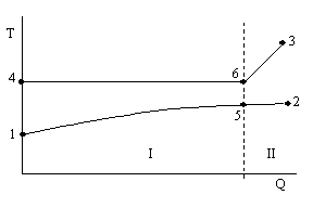
The basis for the used model is the partition into a condenser area and (I) and a super heater area (II) (Fig. 2).

Fig 2: Q-T-Diagram (new model)
1: inlet water
2: outlet water
3: inlet steam
4: outlet condensate
5: intermediate point water
6: begin of condensation of steam
I: condensation area
II: desuperheater area
Following relations describe the heat transfer process exactly
Q = QI + QII (1)
Q = kI AI DtmI + kII AII DtmII (2)
Q: transferred heat
k: k - ratio for areas I and II
A: area
Dtm: logarithmic temperature difference
Known from the energy balance of the steam side are the relation QI/QII as well as the logarithmic temperature difference, because all temperatures can be calculated.
From (2) follows
Q = kI AI DtmI (1 + QII/QI) (3)
as well as
QI/QII = (kI AI DtmI) / (kII AII DtmII) (4)
(4) modified leads to
AII/AI = QII /QI DtmI/DtmII kI/kII (5)
The total area is A comprises of
A = AI + AII = AI (1 + AII/AI) (6)
or
AI = A / (1 + AII/AI) (7)
The transferred heat according to (2) can, therefore, be written as
Q = (kIA) / (1+AII/AI) (1+QII/QI) DtmI (8)
(kI A) equals to the well known value WTKF; QII/QI results from the heat balance
Steam and AII / AI can be calculated from (5).
To be able use equation (8) for
- kI as well as
- kI / kII
relations for full and part load must be derived.
For development of these relations a terminology also according to Rabek is used.
kI / kIv = (1/a1v+ 1/a3v) / (1/a1+ 1/a3) (9)
a1: a- ratio water (line 1)
a3: a- ratio steam (line 3)
Index v: full-load
with
b= a1v/ a3v and (10)
g1 = a1 / a1v as well as (11)
g3= g3/ a3v (12)
results in
kI/kIv = g3(1+b) / (g3/g1+b) (13)
The k - number ratio kI / kII can be formulated as follows.
kI/kII = kIv/kIIv kI/kIv 1/(kII/kIIv) (14)
With (10) and (11) follows
kIv/kIIv = (a1IIv /a1Iv) (1+bII) / (1+bI) (15)
The ratio of the a1- numbers can be set to u1.
The following applies for the ratios kI / kIV and kII / kIIV
kI/kIv = g1I(1+bI) / (1+g1I/ g3IbI) (16)
kII/kIIv = g1II(1+bII) / (1+g1II/g3IIb2) (17)
With g1I »g1II (same medium) and g1II »g3II (single phase medium)
applies to
kI/kII = (1+bII) / (1+bI) (1+bI) / (1+g1I/g3I bI) (18)
The g- dependencies are taken from Rabek sources..
g1I= (m1I/m1vI)0,8 (19)
g3I = (m3I/m3vI)0,33 (20)
With (18) to (20) the system can be solved completely.
3. Calculation
Full load calculations (Load = 0, IFAL = 0) are based on the assumption of a Terminal Temperature Difference (which may be negative also), which is limited due to numerical reasons to -10 K. With assumption of this Terminal Temperature Difference all temperatures are calculated, AII / AI (5) as well as QII / QI are calculated. From the heat transfer relation (8) and the two balances for each fluids the mass flow m3 and kI x A can be determined.
For part load with given kI·A and m3 all temperatures are calculated. For this part load equations(15) as (18) - (20) are used.
The heat transfer area AI (condenser) and AII (super-heater) can be shifted with constant total area A dependent on the thermodynamic conditions..
4. Application
To use the new model a control variable must be modified in the menu for definitions.
Part-load functions according to Rabek
1. k-number - ratio
k/k0 = (1/a10+ 1/a30) / (1/a1+ 1/a3) = (1 + (a10/a30)) / ((a10/a1) + (a10/a30) (a30/a))
with
a10/a30= b
a1/a10= g1 ; a3/a30= g3
k/k0 = (1+b) / (1/g1+ b/g3)
k/k0 = g3(1 + b) / ((g3/g1) + b) (21)
2. Desuperheater/ Evaporator k-number
kI/kII = kv/kE = kv0/kE0 kv/kv0 1/(kE/kE0)
kv0/kE0 = (1/a1E+ 1/a3E) / (1/a1v+ 1/a3v) = a1E/a1v(1 + bE) / (1 + bv) (22)
(kv/kv0) (1/(kE/kE0) = g1(1 + bv) (1 + (g1bE/g3)) / (1 + (g1bv/g3)) g1(1+bE)
= (1 + bv) / (1 + (g1bv/g3)) (23)
kI/kII = kv/kE = (1+bE) / (1+bv) (1+bv) / (1+(g1bv/g3)) (24)
3. Typical values according to Rabek
g3 ~(m3/m03)0,33 and m3/m1 ~m30/m10
g1 ~(m1/m01)0,8
bE~15
bv~2
from (1) k/k0 = (m3/m30)0,33 3/((m3/mv)-0,5 + 2) (25)
from (4) kI/kII = kv/kE = 16/3 (1+2) / (1+ (m3/m30)0,5 2) (26)