
The "EbsWizard" is given under the menu "?". While creating a model, it helps you by providing sample (mostly power plant) models. Some models can be parameterized automatically.
In the first step, select the category of the model:
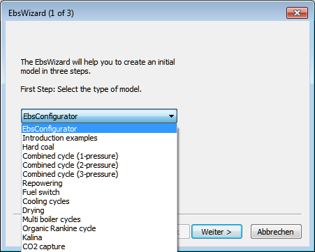
Upon clicking on "Next>" a second selection screen appears, where you can select a specific example for the selected category:
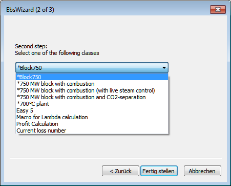
Models marked with "*“ include a mask for the input of some key parameters for the cycle.
Upon a click on "Next>" the corresponding circuit opens. After this screen has been prepared (e.g. "Block 750" under "hard coal"), a third dialog screen appears, where you can set the parameters:
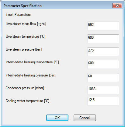
After entering the parameter data, a simulation is performed automatically and the dialog is closed, so that now you can edit the circuit further.
In order to ensure that the parameters of the circuits can be set, an EbsScript with the name "Init" is to be created and the function "wizardBox" is to be used in this EbsScript. A sample EbsScript is given in the file Block750.ebs.
In the category EbsConfigurator, you find two subcategories:
Both include prefab macro models.
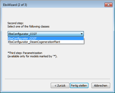
After "Finish>", the corresponding model is opened. The models of EbsConfigurator consist of one active and several passive sheets. The passive sheets contain the individual macro models (e.g. the gas turbines, HRSG, etc. in the case of combined-cycle) out of which the overall model can be configured.
To do so, the respective macro models have to be copied into the active sheet (named <Calculation>).
Arrange the copied macros on the <Calculation> sheet as desired. Then connect the macros to each other automatically by means of the button “Connect auto-connectors” (see Component 132: Automatic connector). The same can be achieved by selecting the menu entry “Edit Connect open connectors”. This results in the creation of all pipes necessary to make your model ready for calculation.
What can be represented by means of this EbsConfigurator "construction kit"?
This construction kit allows to represent three types of steam CHP plants.
a) CHP plant with extraction condensing steam turbine
b) CHP plant with extraction back-pressure steam turbine
c) CHP plant with simple extraction back-pressure steam turbine
a) How to create a model of a CHP plant with extraction condensing steam turbine
To create a model of such a CHP plant you have to use the following macros:
· One Steam boiler from sheet <Boiler>
· One extraction condensing steam turbine from sheet <Condensation_Turbine>
- With or without reheat
- Steam turbine modelled with components 6 or 122
- With or without multiple moving extraction
· One Feed-water tank with or without HP pre heaters 1-2 from sheet <Feedwater>
· With one or without any LP preheated 1-3 from sheet <Condensate>
· Up to 3 steam consumers (HP, IP, LP) from sheet <Consumer>
· One Cooling system from sheet <Cooling>
- Condenser with cooling tower, Component 111 or
- Condenser with direct water cooling
b) How to create a model of a CHP plant with back pressure steam turbine
To create a model of such a CHP plant you have to use the following macros:
· One Steam boiler from sheet <Boiler>
· One back-pressure steam turbine from sheet <Backpressure_Turbine>
- With or without reheat
- Steam turbine modelled with components 6 or 122
- With or without multiple moving extraction
· One Feed-water tank with or without HP pre heaters 1-2 from sheet <Feedwater>
· With one or without any LP preheated 1-3 from sheet <Condensate>
· Up to three steam consumers (HP, IP, LP) from sheet <Consumer>
c) How to create a model of a CHP plant with simple back pressure steam turbine
To create a model of such a CHP plant you have to use the following macros:
· One Steam boiler from sheet <Boiler>
· The simple back-pressure steam turbine from sheet <Backpressure_Turbine>
· One Feed-water tank without any HP pre heaters from sheet <Feedwater>
· The condensate system with no LP pre heaters from sheet <Condensate>
· The (only this!) steam consumer "Consumer for simple BPT" or "Consumer LP" from sheet <Consumer>
d) Additional notes
1) The necessary macros from the sheets <Additionals> and <PowerCalculation> are already included in the prepared calculation sheet <Calculation>.
2) Each turbine macro has the following connectors or inputs / outputs resp.:
Which of these connectors will be used or connected resp. depends on the macros selected from the sheets <Feedwater>, <Condensate> and <Consumer>. Connectors which fit together will be connected via automatically generated pipes, the others will remain unconnected.
3) The internal efficiencies of the extraction steam turbines consisting of components 122 have to be entered manually. The automatically calculated internal efficiency according to "SCC" (Spencer Cotton Cannon) will be included in the next patch or release.
4) In the case of the simple back-pressure turbine, only one consumer is possible. Here you can choose between the consumers "Consumer for simple BPT" and "Consumer LP".
5) After having copied all of the macros to the Calculation sheet, click the "Connect auto-connectors" button, to create all connecting pipes. After this it will be necessary to move the connected macros to create a well arranged model or to avoid overlapping pipes. Maybe you want to insert some new points in some pipes (shortcut is the "<" key).
Which rules have to be followed?
See also the passive sheets <Method_english> respectively <Method_german>.
WWhat is the purpose of the sub profiles?
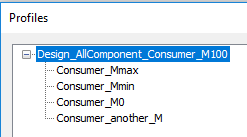
b) In the case of the CHP plant with extraction condensing steam turbine, there are four sub profiles:
· Consumer_Mmax -> consumer with maximum steam quantity
· Consumer_Mmin -> consumer with minimum steam quantity
· Consumer_M0 -> consumer with no steam, e. g. pure condensation operation
· Comsumer_another_M -> consumer with steam quantity between minimum and maximum
The profiles are created automatically by means of the button "Profile Structure". The specification values of all macros have to be adjusted by you for all profiles for your special requirements.
c) In the case of the CHP plant with back-pressure steam turbine, there are three sub profiles:
· Consumer_Mmax -> consumer with maximum steam quantity
· Consumer_Mmin -> consumer with minimum steam quantity
· Comsumer_another_M -> consumer with steam quantity between minimum and maximum.
The profiles are created automatically by means of the button "Profile Structure". The specification values of all macros have to be adjusted by you for all profiles for your special requirements.
What are the limitations ?
a) In the case of the CHP plant with extraction condensing steam turbine and “Cooling_tower_system“, it is advantageous to set the design pressure for the condenser to 80 - 100 mbar. If the design pressure would be higher (e.g. 200 mbar), the condenser performance might be too small in part load operation, so that the simulation might terminate with an error message at the cooling tower: “The cooling water input stream is out of range (P, M or H).” In this case, the upper temperature difference of the condenser can be reduced, and/or the electrical output of the steam turbine can be increased, and/or the design can be done again with reduced mass flow M100 (condenser is enlarged).
b) Some connectors (component 132) of the macros Boiler, Steam Turbine, Condensate System and Feed Water System must be preset with M=0. These connectors are those that can remain unconnected in the overall model (they have no pipe connected). If you supply values M>0, this macro must not be used for an overall model anymore. Use a new copy out of the sheets then.
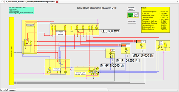
Example of a CHP plant created with the EbsConfigurator:
- With reheat
- With HP-Preheater 1
- With 3 moving extractions
- Components 122 used to represent the turbine
- With HP- IP- and LP-consumer
- With LP-preheater 1 and feed water heat exchanger
- QEL of turbine set to 300 MW
- With Condenser with cooling tower
- HP consumer steam flow set to 150 t/h
- IP consumer steam flow set to 100 t/h
- LP consumer steam flow set to 50 t/h
