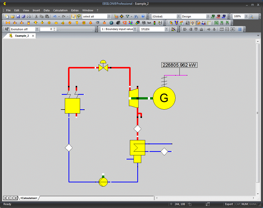

In this chapter we shall map a simple water/steam cycle.

We start with the steam generator. Click on the steam generator symbol (the next entry in the component bar) and select "Steam generator (5)". Move the mouse pointer to the position where you want to insert the steam generator and click on the left mouse button. A steam generator symbol is inserted in the drawing.
The steam generator you just have inserted is still highlighted. You can now proceed in the following ways:
Now you are in normal edit mode.
The next component you are going to insert is a control valve. This is necessary, because in the design mode the steam generator determines the life steam pressure and the steam turbine determines its inlet pressure. Therefore, a pressure separator, namely the control valve is required. To insert this component, click on the throttle in the component bar and select "Control valve(14)".
For your further work, it may be convenient to enlarge you drawing. You can do this by using the zoom combo box in the tool bar (enter a number or select one), or by clicking the "100 %" button to the right of the combo box. This button always resizes your drawing to fit to the window, if it is maximized. If you want to expand your drawing, use the ">>" button to enlarge the visible region. To enlarge a section of the drawing, draw a catching frame with the right mouse button (keep the right mouse button pressed down until the rectangle indicates the section you want to enlarge).
In the next step, draw a connection between the steam generator and the control valve. This is very easy in EBSILON®Professional:
The connection pipe will be drawn and normalized automatically (shown as rectangular). If it is not normalized, activate the checkbox ”Normalized Pipes” by selecting "View →Normalized pipes" in the menu bar. The red lines indicate the steam lines.
The meaning of the connection points of a component can be retrieved by the ”Component Properties” window (double-click on the component). In this screen on the right, point the mouse pointer to a component to know what it is.
In the next step, insert the steam turbine. Click on the turbine icon in the component bar and select "Steam turbine(6)". Draw a connection from the control valve outlet to the steam turbine inlet. You will find the right connection point at the turbine, because EBSILON®Professional does not allow you to connect at a wrong one.
Insert the generator by selecting the entry ”Insert→Component→Motors/Generators→Generator”. Connect the mechanical shaft (thick green line) to the turbine shaft outlet. Additionally, double-click on the electric outlet and draw a short line (double-click to finish the line). This is useful, because you surely want to connect a value field later to display the generator power.
The steam turbine condenser can be found in the heat exchanger section (7th entry in the component bar). Insert it below the turbine and connect one of the turbine's steam outlets to the steam inlet of the condenser.
Connect the short water pipes (the blue ones) at the cooling water inlet and outlet (the connection points on the far right). This is required for the specifying and displaying the cooling water states.
The last component is the pump. It is the sixth entry of the component bar.
Connect the condenser's water outlet (bottom) to the pump inlet and the pump's water outlet to the feed water inlet of the steam generator.
Now the drawing work is ready and we can try to perform a calculation.