EBSILON®Professional Online Documentation


|
Line connections |
|
|
|
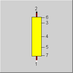
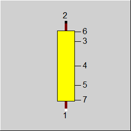
1 |
Flue gas inlet (hot side) |
|
|
2 |
Flue gas outlet (hot side) |
|
|
3 |
Heat flow to bundle Connection to attached main heating surface, component 89 |
|
|
4 |
Connection to attached auxiliary heating surface 1, component 91 |
|
|
5 |
Connection to attached auxiliary heating surface 2, component 91 |
|
|
6 |
Radiation flow to downstream heating surface component 89 |
|
|
7 |
Radiation flow to upstream heating surface component 89 |
|
General User Input Values Characteristic Lines Physics Used Displays Example
Together with components 89 (steam generator, main heating surface) or 91 (steam generator, auxiliary heating surface) respectively, component 88 allows the geometry based calculation of the heat exchange in the heating surfaces of a steam generator.
Component 88 represents a flue gas zone, which houses a main heating surface (component 89) and up to two auxiliary surfaces. PIN 3 of the flue gas zone (component 88) should be
connected with PIN 3 of a component 89 (main heating surface). PIN 4 or PIN 5 of component 88 can be connected with PIN 3 of component 91. In addition, the radiation flow from the flue gas volume in the zone to the upstream and / or downstream heating surface component 89 can be taken into account. For this purpose, PIN 7 can be connected with PIN 5 of the main heating
surface (component 89) in the upstream flue gas zone and correspondingly PIN 6 with PIN 4 of component 89 in the downstream zone.
The behaviour of component 89 concerning heat transfer and radiation resembles that of component 90 (combustion zone), but there is no reaction, especially no post-combustion.
Extensions for the Pressure Drop Calculation of the Flue Gas Side (for Components 88 and 89)
In Component 89, the pressure drop calculation of the flue gas side can be specified as Kernel expression, EDPO. As geometrical details of the heating surface are specified in Component 89, it is possible to access the corresponding specification values (like e.g. pipe diameter, partition, details on fins, etc.) and to implement an own pressure drop calculation (e.g. according to manufacturer information) in the Kernel expression EDPO.
The pressure drop on the flue gas side is calculated in Component 89 and transferred to Component 88. In Component 88 there is a flag for this, FDP, which switches between the previous pressure drop calculation according to Bernoulli’s principle and EDPO of Component 89.
For the flue gas zone are additionally as result values
• the flow velocity in free cross-section as VELF
• the volume of the VOLFG flue gas zone
• the wall surface of the smoke zone AWS
output.
The calculation model first balances the mass flow, momentum and energy flows
with the indices
Concerning enthalpy, mass flow and pressure, the component assumes, that H1 or H2, M1 or M2, P1 or P2 are given on the attached lines. In each case the missing value is calculated.
Pressure drop limitations in off-design (Extras --> Model Options--> Calculation -->Relative pressure-drop maximum) :
As the pressure drop rises quadratically with the mass flow, pressure drops that are significantly too high can quickly arise in the event of a transgression of the nominal mass flow. These will then cause phase transitions and convergence problems. For this reason, pressure drop limitations have been installed.
Note: Improvements of Convergency:
In certain cases, there were cycles that required 1000 or more steps to convergency. Therefore, certain steps were performed to improve the convergency behaviour.
One step was a test to include the lower calorific value and the material composition into matrix solution. By default, the matrix equations are restricted to mass flow, enthalpies and pressures. The test was performed with the components 4, 15, 18, 25, 33, 60, 80, 88 und 90. The result was an improvement of convergency in some cases, but a worsening in other cases.
Therefore, this feature will not be used by default. If anyone likes to test it, you may activate it by setting the level of integration of material equations to " in simulation only" (“Extras”, ”Model options”, “Iteration” ).
The heat flow to main and auxiliary heating surface in the flue gas zone are calculated in the components 89 and 91 and transferred to component 88 via the logic lines. If upstream or downstream main heating surfaces are attached, in component 88 the corresponding radiation flow are calculated:
QR_6 = PHI6_I*CS*EBS3_I*(1-EBS6_I)*LAMBDA*(TRADH6**4-TRADL6**4)*BEW3
QR_7 = PHI7_I*CS*EBS3_I*(1-EBS7_I)*LAMBDA*(TRADH7**4-TRADL7**4)*BEW3
Form factors PHI, emissivities EBS and evaluations BEW are calculated in the respectively connected modules. The radiation temperature of the emitting zone 88 is the average of in- and outlet temperature.
TRADH6=TRADH7=(T1+T2)/2+273.15
The radiation flows are always positive, that is there is no radiation into the flue gas originating from surfaces with a possibly higher wall temperature. The radiation temperature of the heating surfaces corresponds to the average wall temperature.
TRADL6 = TWAND6
TRADL7 = TWAND7
Currently there is no identification mode for component 88.
Besides the main heating surfaces there frequently are smaller heating surfaces in the form of water or steam cooled parts of the construction (supporting tubes, cooled walls) in a flue gas zone. They have the same flue gas in- and outlet conditions as the main surface, but usually are integrated in another part of the water / steam path. These auxiliary surfaces are represented by component 91.
Main and auxiliary heating surfaces contribute to the heat exchange within the zone 88, but radiation exchange with neighbouring zone only affects main surfaces, component 89.
An auxiliary surface should be used only if a main surface is already attached.
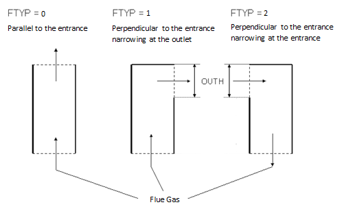
The arrangement of inlet and outlet area of the flue gas zone essentially influences the calculation of the form factor PHI. To represent the different types of steam generator design (single-pass boiler, double-pass boiler) with or without direction changes in the flue gas path the specifications values OUTH and FTYP can be used. Their use is shown in the diagram given below:
|
FDP |
Relative heat loss in the flue gas zone caused by radiation to outside. Like in Parent Profile (Sub profile option only) Expression =0: Calculated by DP12N =1: Using value computed in the comp. 89 (see "General") |
|
DP12N |
Pressure loss 12 in design mode. If design mode is set, the prescribed value is used. If part-load is set, pressure will be corrected with mass flow and specific volume. |
|
DQLR |
Relative heat loss in the flue gas zone caused by radiation to outside. DQ = DQLR*QNEN |
|
FMODE |
Flag for calculation mode design/off-design =0: Global |
|
ZW |
Width of the flue gas zone ZW and ZD are the dimensions of the cuboid-shaped flue gas zone perpendicular to the flow direction of the flue gas |
|
ZD |
Depth of the flue gas zone ZW and ZD are the dimensions of the cuboid-shaped flue gas zone perpendicular to the flow direction of the flue gas |
|
ZH |
Height of the flue gas zone ZH is the dimension of the cuboid-shaped flue gas zone in the flow direction of the flue gas |
|
OUTH |
Height of the flue gas outlet, ignored, if FTYP = parallel to inlet. |
|
FTYP |
Arrangement of the flue gas outlet cross-section Like in Parent Profile (Sub profile option only) Expression =0: parallel to inlet =1: perpendicular to inlet, contraction at outlet =2: perpendicular to inlet, contraction at inlet |
|
M1N |
Flue gas mass flow inlet (nominal) |
|
V1N |
Specific volume of the flue gas inlet (nominal) |
|
QN |
Heat transferred from flue gas (nominal) |
The identification values marked in blue are reference values for off-design mode. These values are referred to for the actual off-design values used in the equations respectively. If these identification values are stream data, then these values are often taken from attached pipes or calculated values.
The inputs for nominal values are also black in a Sub profile for a given component, in case the user selected the local off-design option for that component and in the nominal values were saved into that component.
No characteristic lines are used.
|
Design (Simulation flag: GLOBAL = Design and FMODE = Design) |
||
|
|
P2 = P1-DP12N |
|
|
Off-design (Simulation flag: GLOBAL = Off-design or FMODE = off-design) |
||
|
|
DP12 = DP12N * V1/V1N * (M1/M1N)**2 P2 = P1 - DP12 |
|
|
All cases
|
||
|
|
M1 = M2 -M1*H1+M1*H2+M3*H3+M4*H4+M5*H5+M6*H6 TRADL6 = TWAND6 TRADL7 = TWAND7 VERL = QNEN*QVERL Regula Falsi: (Outlet temperature)
TRADH6 = (T1+T2)*.5+T00 TRADH6 = (T1+T2)*.5+T00 LAMBDA=0.85 (empirical adjust factor) QR_6 = PHI6_I*CS*EBS3_I*(1-EBS6_I)*LAMBDA*(TRADH6**4-TRADL6**4)*BEW3 QR_7 = PHI7_I*CS*EBS3_I*(1-EBS7_I)*LAMBDA*(TRADH7**4-TRADL7**4)*BEW3
QSUMRG= Q3+Q4+Q5+QR_6+QR_7+VERL
H2 = H1 - QSUMRG/M1
END Fixed point iteration 1
H6 = QR_6 H7 = QR_7
|
|
|
|
|
|
 |
Display Option 1 |
Click here >> Component_88 Demo << to load an example.