EBSILON®Professional Online Documentation


|
Line connections |
|
|
|
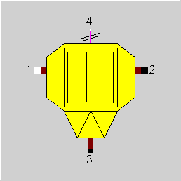
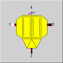
1 |
Flue gas inlet |
|
|
2 |
Flue gas outlet (filtered) |
|
|
3 |
Dust (Flue gas) outlet (filtrate) |
|
|
4 |
Required electrical power |
|
General User Input Values Characteristic Lines Physics Used Displays Example
Component 85 handles energy and mass balances of an electrostatic precipitator.
You can choose from four calculation modes: See Notes for FDUST (User Input Values)
The necessary electric power can be calculated from the normalized electrical power and will be included in the energy balance.
The electrostatic precipitator considered gaseous ashes.
"Standard“ quantities
In practice, certain quantities are often related to “standard conditions“; depending on the context, different standards are used.
The options for determining the standard conditions (to specify quantities related to standard conditions ) have been extended :
The input for FNORM determines the reference pressure and reference temperature:
Adopting the reference values from the general settings is not reasonable because other results might be generated on another computer.
The flag FNORMW decides if for determining the standard volume only the dry fraction of the gas is to be considered, or if the water fraction is to be taken along.
The flag FNORMO2 enables a conversion to a reference oxygen concentration. There are the following variants:
• FNORMO2=0: Actual O2 concentration is kept, whereby this concentration refers to the dry or humid flue gas depending on the setting
of the flag FNORMW.
• FNORMO2=1: the reference concentration is taken over from the model settings, whereby this concentration refers to the dry or humid flue gas depending on the setting
of the flag FNORMW.
• FNORMO2=2: the reference concentration is taken from the component specification value O2REF, whereby this concentration refers to the dry or humid flue gas
depending on the setting of the flag FNORMW.
• FNORMO2=3: : the reference concentration is taken over from the model settings, whereby this concentration always refers to the dry flue gas, independent of the
flag FNORMW.
• FNORMO2=4: the reference concentration is taken from the component specification value O2REF, whereby this concentration always refers to the dry flue gas,
independent of the flag FNORMW.
Note:
In this component, the specification value M2DV2N refers to the normalized concentration (in the design case), whereas result value M2DV2 was not converted
to standard conditions. This has been changed : M2DV2 is the dust concentration at the outlet converted to standard conditions (in the current load case).
A new result value RM2DV2 has been implemented for the actual dust concentration.
|
FDUST |
Flag for defining the filtering
Like in Parent Profile (Sub Profile option only) Expression =0: specified by total separation ratio M3M1N =1: specified by dust exhaust concentration M2DV2N =2: Dust concentration in the exhaust gas, calculated from geometry (ACOLL, MAXFGB, ACTFGB) - " Deutsch formula" =-1: Identification mode - |
|
M3M1N |
Total separation ratio (nominal), e.g. (fly ash of line 3) / (fly ash of line 1) |
|
M2DV2N |
Normalized molar dust exhaust concentration (nominal) |
|
IPSDUST |
Index of pseudo measurement point for dust concentration (only in identification mode) |
|
ACOLL |
Dust collecting area |
|
SIZCON |
Constant (dust sizing constant) in the modified |
|
MAXFGP |
Maximum number of dust collecting areas, which can be in operation |
|
ACTFGP |
Actual number of dust collecting areas, which are in operation |
|
QM2D |
Specific electrical power, e.g. required electrical power per fly ash mass flow |
|
DP12N |
Pressure drop between line 1 and 2 (nominal) |
|
FMODE |
Calculation mode design / off-design Expression =0: GLOBAL =1: Local off-design i.e. always off-design mode, even when the model is calculated in the design mode. |
|
FNORM |
Flag to define a combination of reference pressure and reference temperature
Expression =0: EBSILON default (1bar, 15°C) =1: DIN 1343 (1.01325bar, 0°C) =2: ISO 2533 (1.01325bar, 15°C) =3: DIN 1945 (1bar, 20°C) =4: 1bar, 0°C (use for line result MGNM3) =5: 1.01325bar, 20°C =6: 14.696psia, 60F (often used for SCF( standard cubic feet ))
=-1: Use measurement points for reference pressure and temperature =-2: Do not normalize but use actual pressure and temperature |
|
FNORMW |
Consideration of water for normalized concentration Expression =0: Keep actual water concentration (wet) =1: Neglect water concentration (dry) |
|
FNORMO2 |
Flag to define scaling to reference O2 concentration Expression =0: Keep actual O2 concentration (no scaling) =1: Scale to molar O2 concentration from model settings =2: Scale to molar O2 concentration as specified in O2REF =3: Scale to dry molar O2 concentration from model settings =4: Scale to dry molar O2 concentration as specified in O2REF |
|
O2REF |
Reference O2 concentration (molar) |
|
M1N |
Inlet mass flow (nominal) |
|
V1N |
Specific volume at the inlet (nominal) |
|
T1N |
Flue gas temperature at the inlet (nominal) |
The identification value marked in blue is the reference value for the off-design mode. The actual off-design values refer to the values used in the equations.
|
Characteristic line 1: Removed fly ash ratio M3M1/M3M1N = f (M1/M1N) |
|
X-axis 1 M1/M1N 1st point |
|
Design case (Simulation flag: GLOBAL = Design case and FMODE = GLOBAL) |
||
|
|
F = 1.0 ZWIP = 1.0 |
|
|
Off-design case (Simulation flag: GLOBAL = Off-design or FMODE = Local off-design)
|
||
|
|
FDUST = 0 or 1 F = (M1/M1N) ** 2*(V1/V1N) ZWIP = f(M1/M1N) from characteristic line FDUST = 2 or -1 F = (M1/M1N) ** 2*(V1/V1N) ZWIP = 1-EXP(SIZCON*ACOLL/(VX(1)*DX(1)))**0.5 |
|
|
All cases
|
||
|
|
P2 = P1 DP12N * F P3 = P2
SUM1: sum of all solid mass concentrations of line 1
DQ = QM2D*SUM1 *M1 H4 = DQ H11 = H1+DQ/D1 T2 = f(H11,P1) T3 = T2 H2 = f(T2,P2) H3= f(T3,P3)
If FDUST=0 then M3 = M3M1N*ZWIP*SUM1*M1 else if FDUST=1 then VX2N: Specific volume in line 2 under normalized conditions M3 = SUM1*M1-M2DV2N*ZWIP*VX2N*M2 else if FDUST=2 then M3=ZWIP*SUM*M1 else if FDUST= -1 then ACOLL = VX(1) * DX(1)/SIZCON* D2DV2 from pseudo measurement point given by IPSDUST M3=ZWIP*SUM*M1 endif
M2 = M1-M3
Mass concentrations from mass balance of the components |
|
 |
Display Option 1 |
Click here >> Component 85 Demo << to load an example