
|
Line connections |
|
|
|
1 |
Inlet |
|
|
2 |
Outlet |
|
General User Input Values Physics Used Displays Example
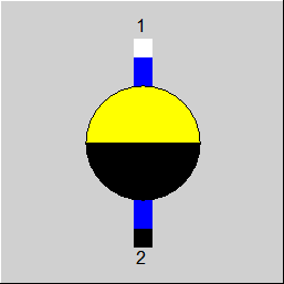
This component can be used as a pressure separator between the pre heaters for feed water.
The pressures before (P1) and after (P2) the condensate trap are defined by other components (mostly component 33, Start Value). The mass flows
M1 = M2
are retained and an isenthalpic throttling
H1 = H2
is taken as the basis. Normally, the temperature changes owing to the pressure reduction:
T1(P1,H1) is not equal to T2(P2,H2)
Similar components:
Component 14 (control valve):
The control valve is also a component that separates the pressure. This function can be used as component 42.
Using component 42, or also 14, to separate the pressure stages between the feed water heaters does not introduce the secondary flow of the condensate between the condenser part and the possible sub-cooler but it always introduces this flow after the after-cooler, located downstream. If you do not pay attention to this serious problem, convergence will occur.
No specifications necessary.
|
All cases |
||
|
|
H2 = H1 T2 = f(P2, H2) M2 = M1 Q2 = Q1
|
|
 |
Display Option 1 |
Click here >> Component 42 Demo << to load an example.