
EBSILON®Professional Online Documentation


|
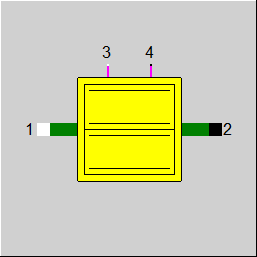
Line Connections |
|
|
|
1 |
Shaft inlet |
|
|
2 |
Shaft outlet |
|
|
3 |
Electric power inlet |
|
|
4 |
Electric power outlet |
|
General User Input Values Physics Used Characteristic Lines Results Displays Example
Component 171 can be used to model a fly wheel energy storage. The energy is thereby stored in mechanical form as the rotational energy of a rotor. The component features shaft and electric power inlet and outlet PINs for charging / discharging. The energy content of the storage is proportional to the rotation speed of its rotor. Thus, an acceleration acts as a charging and slowing down as a discharging. By means of this component also an acceleration of a rotating mass, e.g. of a turbine rotor, can be balanced.
The key parameter for the storage computation is the moment of inertia MOI of the storage rotor. In case of self-discharge, i.e. the storage is not charged from any sources nor discharged to any sinks the parameter LRATE controls the loss rate of rotation speed. At charging / discharging (can be done also simultaneously) the efficiency values ETAM, ETAE control the corresponding mechanical, electrical losses.
|
FINST |
Flag: Determination of transient calculation modes |
|
FINIT
|
Flag: Initializing state =0: Global, which is controlled via global variable "Transient mode" under Model Options =1: First run -> Initializing while calculating steady state values |
|
MOI |
Rotor moment of inertia |
|
LRATE |
Loss rate of rotation speed (portion of rot.speed lost per second at self-discharge). This value is relevant only if no power is coupled as input or output (PINs 1-4) |
|
RSBEG |
Rotation speed at the beginning of the time step or initial rotation speed (if FINIT=1) |
|
ETAM |
Mechanical efficiency |
|
ETAE |
Electrical efficiency |
|
TIMETOT0 |
Total time at start of calculation |
| RSMIN | Minimal rotation speed |
| RSMAX | Maximal rotation speed |
|
RSEND |
Rotation speed at current time step end |
|
ECEND |
Energy content at current time step end |
|
TIMETOT |
Total time at end of calculation |
The calculation of the component 171 is based on the equivalence between the rotation speed and the energy content and on the transient energy balance of the storage. The energy content of the storage can be computed as
\[ E_{rot} = \frac{1}{2} I \omega^2 = \frac{1}{2} I (2 \pi n_{rot})^2 \]
With \(I\) being the moment of inertia, \(\omega\) the angular velocity and \(n_{rot}\) the rotation speed respectively.
The change of the system energy content in a transient time step can be written as
\[ \frac{E_{2} - E_{1}}{dt} = q_{el,in} \eta_{el} \eta_{m} + q_{sh,in} \eta_{m} - \frac{q_{el,out}} {\eta_{el} \eta_{m}} - \frac{q_{sh,out}} {\eta_{m}} \]
in case of charging / discharging or as
\[ \frac{E_{2} - E_{1}}{dt} = -q_{loss} \]
in case of self-discharging. Here \(E_1\), \(E_2\) denote the energy content at the beginning and at the end of the time interval \(dt\). \(q_{el,in}\), \(q_{el,out}\) are the incoming and the outgoing electric power values. \(q_{sh,in}\), \(q_{sh,out}\) are the incoming and the outgoing shaft power values. \(\eta_{el}\), \(\eta_m\) are the electric and mechanic efficiencies. \(q_{loss}\) denotes the power loss at self-discharging and is computed as
\[ q_{loss} = \frac{1}{2} \frac{I}{dt} ((2 \pi n_{1}) ^2 - (2 \pi n_{2})^2) \]
with \(n_1\), \(n_2\) being the values of rotation speed at the beginning and at the end of the time interval. The value at the end of the time interval is here computed as
\[ n_{2} = n_{1} (1 - R_{loss} dt) \]
with \(R_{loss}\) being the loss rate of rotation speed (specification value LRATE).
 |
Display option 1 |
Click here>> Component 171 Demo << to load an example.