
EBSILON®Professional Online Documentation


|
Line Connections |
|
|
|
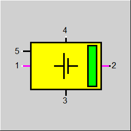
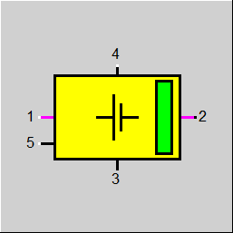
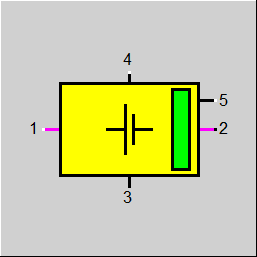
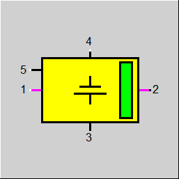
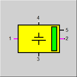
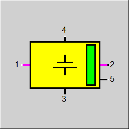
1 |
Power Inlet (optional, for series connection of batteries) |
|
|
2 |
Power connection (> 0 for discharge, < 0 for charge) |
|
|
3 |
Power Loss |
|
|
4 |
Connection to aging module |
|
|
5 |
Control inlet (to control the operating mode |
|
General User Input Values Physics Used Characteristic Lines Results Display Example
This component represents a battery consisting of individual cells with a nominal capacity CCELLN and a nominal voltage UCELLN. The actually available capacity decreases according to a factor SOH (state of health) that is specified to the battery by the aging module via Logic Pin 4. The prevailing state of charge of the cell SOC must remain between the limits SOCMIN and SOCMAX.
The component Battery consists of NBANK banks connected in parallel that consist of NRACK racks connected in parallel in each case. Each rack consists of NMOD modules connected in series. Each module consists of NPAR * NSER modules (connected per NPAR in parallel and NSER in series).
When discharging the battery, the terminal voltage decreases under its nominal value down to a minimum value UCOCELL (cut-off voltage). Here the current can rise up to the short circuit current ISCCELL.
The terminal voltage as a function of the discharge current and of the state of charge (SOC) is defined by a characteristic field CUACT that consists of 20 characteristic lines with the prevailing state of charge as parameter. Instead of the characteristic field, it is also possible to calculate with a constant internal resistance of the cell, which can optionally be specified directly or can be calculated from the short circuit current.
The component can be applied both in electric circuits, where it calculates the current based on the resistances in the electric circuit, and in control loops that require the current to be specified externally. It is also possible to define the current by specifying the desired power on Logic Inlet 5.
To display the aging of the battery, an external aging module has to be connected to Logic Inlet 4. Via this logic inlet, the battery receives its respective prevailing SOH (”state of health“) from the aging module. It is defined as the ratio of the current to the original capacity of the battery. The aging module, in turn, can access the the data of the battery via this logic pin and calculate the aging.
In most Ebsilon components, the fluid flows into the component via Pin 1 and out of the component via Pin 2. In the case of the component Battery, however, the same pin (namely Pin 2) is used for charging and for discharging.
As, topologically, it is an outlet, positive values are displayed for the power when discharging. The charging process is displayed by means of negative values. On the one hand, this is closer to reality (as in reality the same cables are used for charging and discharging) and on the other hand it facilitates the modeling.
Nevertheless, there is also an electric inlet (Pin 1) in this component, which, however, is optional and not used for charging but for connecting another battery. This way, several Components 158 can be connected in series. In doing so, the voltages will add up while the current remains the same through all batteries. With the exception of the last one, all batteries must be operated in the mode FOP=-1 (“Current given externally“) as the last battery carries out the calculation for the overall package and writes the current onto the line.
Pin 3 is a logic outlet for the losses. These are calculated by the battery. Here both the losses occurring in the battery and the power required for the cooling can be considered (see Chapter FLOSS-Loss Calculation).
Pin 4 is the logic inlet for the connection of the aging module: via this connection, the aging module receives the required data of the battery. The aging module calculates the new SOH (state of health) at the end of the respective time step and communicates it to the battery via the logic line at the beginning of the next time step.
Pin 5 is the logic inlet for the control. The desired power is specified on this line. When the battery is to be charged, a negative value has to be specified. Whether the desired power can be achieved depends both on the state of charge of the battery and on the current:
FOP - Operation Mode:
FUTHERM - Method for Calculating the Terminal Voltage:
This flag serves to define the correlation between terminal voltage and current. By default, the calculation is effected with a constant internal resistance. However, it is also possible to store a characteristic field.
FLOSS - Loss Calculation:
Losses are calculated by the component itself and are written as heat on Logic Outlet 3. There are the following variants for calculating the losses that occur during the operation of the battery:
QLOSSOP = (UTOTN – U2) * I2
Please note that the loss becomes positive at all times because while charging I2 < 0 and U2 > UTOTN.
Here U2, I2 and Q2 are voltage, current and power at the outlet and the proportionality factor LOSS is a specification value.
Moreover, for the losses it is also possible to consider the auxiliary power QLOSSC of the air conditioner required for cooling the batteries. As it depends on the ambient temperatures, there is a characteristic line CQLOSSC for this purpose. This characteristic line is used both in the design case and in off-design. Therefore the design temperature of the air conditioner (i.e. the temperature where the characteristic line has the value 1) does not have to be consistent with the design case of the overall model.
It is assumed that the air conditioner can be operated independently of the battery. Therefore the auxiliary power is also calculated when the battery is turned off.
FTIMELIM - behaviour when Reaching the Limits:
This flag allows to set the behaviour for a transient calculation, e.g. in the context of a time series.
Within the time step, the component carries out a steady-state calculation as a rule, i.e. no time dependencies are considered. Only when calculating the result values SOCNEW (new state of charge at the end of the time step) and DCHARGE (change of charge in the time step) does a time dependency come into play.
As long as SOCNEW is within the valid range between SOCMIN and SOCMAX, FTIMELIM has no effect. However, if SOCNEW exceeds a limit, there are the following options:
In both cases, SOCNEW is then set to the respective limit value (SOCMIN or SOCMAX).
When carrying out a time series calculation, after calculating a time step the result value SOCNEW is then copied onto the specification value SOC for the next time step.
Note: No FMODE
A flag FMODE for switching over between design and off-design mode does not exist in this component as there are no nominal values for this component that might be calculated by Ebsilon in the context of a design calculation.
Specification Values for the Operation
These specification values are only relevant for the operation with power demand (FOP=3).
CRATEN: nominal value for the charge rate (CRATE)
The charge rate indicates the proportion of the capacity per time unit that is charged and discharged respectively. For instance: at a CRATE of 0.5 A/Ah, the SOC (state of charge) of the battery is increased and decreased respectively by 0.5 in one hour.
The charge rate results from the nominal value CRATEN and the characteristic line CCRATE as a function of the state of charge. By default, this characteristic line is designed is such a way that the charge rate is already reduced when approaching SOC=1.
DCRATEN: nominal value for the discharge rate (DCRATE) (optional)
Only enter a value here if another rate is to be used for discharging than for charging. Otherwise the discharge rate is equated with the charge rate.
STHR: threshold value for charging
Here you can enter a threshold value that has to be exceeded for the battery to switch over to “Charge” mode.
Specification Values for the Geometry
NPAR: number of parallel cells per module
NSER: number of serial cells per module
NMOD: number of modules per rack
NRACK: number of racks per bank
NBANKS: number of banks in the component
Specification Values for Capacity and Voltage
UCELLN: nominal voltage of a cell
CCELLN: nominal capacity (maximum charge) of a cell
RINTCELL: internal resistance of a cell
ISCCELL: short circuit current (max. possible current) of a cell
QMAX: maximum power of the total battery
Specification Values for the State
SOC: current state of charge
SOCMIN: min. admissible state of charge
SOCMAX: max. admissible state of charge
The “state of health“ (SOH) is not managed in the battery but in the aging module. The battery only shows in the result values which SOH the calculation
was carried out with.
Specification Values for the Loss Calculation
LOSS: loss factor (proportionality factor at FLOSS=1 or 2)
QLOSSCN: nominal value for the power of the air conditioner
This value is multiplied by the value of the characteristic line CQLOSS which depends on the ambient temperature.
TAMB: ambient temperature (for FSTAMB=0)
ISUN: link to Component 117 (for FSTAMB=1)
Result Values for the Operation:
RCRATE: applied charge and discharge rate respectively
UCELL: present voltage of a cell
UTOT: present total voltage
ICELL: present current through a cell
ITOT: present total current
QTOT: total battery power
Result Values for the State:
SOCNEW: new state of charge at the end of the time step
SOH: state of health used for the calculation
CTOT: total capacity at the current state of health
DCHARGE: change of charge during the time step
DCHARGECTOT: Charge change relative to total capacity
Result Values for the Loss Calculation:
RTAMB: applied ambient temperature
QLOSSOP: loss due to the operation of the battery
QLOSSC: loss due to the air conditioner
QLOSSTOT: total loss
Other Result Values :
UTOTN: nominal voltage of the total battery
UUN: ratio of present to nominal voltage
IISC: ratio of present to short circuit current
RRINTCELL: used internal resistance, one cell
RRINTTOT: used internal resistance of the total battery
RQMAX: calculated maximum power of the battery
This result value is calculated from the internal resistance assuming that it is constant. If this is not the case (possible at FUTERM=3), this value is
only an approximation.
QQMAX: Ratio actual power / maximum power
CRATE: relative charge rate as a function of the state of charge
CQLOSSC: Relative power of the air-conditioning system as a function of the ambient temperature
FCUTERM: Characteristic diagram consisting of characteristic curves CUTERM_n for the relative terminal voltage as a function of the relative cell current intensity (referred to the short-circuit current ISCCELL) with the state of charge SOC as parameter.
|
FOP |
Flag: Operation mode = -1: current given externally |
|
CRATEN |
Charge rate (nominal) |
|
DCRATEN |
Discharge rate (nominal) (optional, if different from CRATE) |
|
STHR |
Switching threshold for charging |
|
NPAR |
Number of parallel cells per module |
|
NSER |
Number of serial cells per module |
|
NMOD |
Number of modules per rack |
|
NRACK |
Number of racks per bank |
|
NBANK |
Number of banks |
|
UCELLN |
Nominal voltage of cell |
|
CCELLN |
Nominal capacity (maximum charge) per cell |
|
FUTERM |
Flag: Method for calculation of terminal voltage |
|
RINTCELL |
Internal resistance of cell |
|
ISCCELL |
Short circuit current per cell |
|
QMAX |
Maximum power of total battery |
|
SOC |
Present state of charge |
|
SOCMIN |
Minimum state of charge |
|
SOCMAX |
Maximum state of charge |
|
FTIMELIM |
Flag: Handling of limit achievement in time interval = 0: Reducer power to avoid exceeding limit |
|
FLOSS |
Flag: Switch for heat losses |
|
LOSS |
Factor for heat losses |
|
QLOSSCN |
Flag: Handling of limit achievement in time interval |
|
FSTAMB |
Definition of ambient temperature =0: Given by parameter TAMB |
|
TAMB |
Ambient temperature |
|
ISUN |
Index for solar and ambient Parameters |
|
RCRATE |
Applied change rate |
|
UCELL |
Terminal voltage of cell |
|
UTOT |
Total voltage |
|
ICELL |
Present current of cell |
|
ITOT |
Total current |
|
QTOT |
Total battery power |
|
SOCNEW |
New state of charge |
|
SOH |
Applied state of health |
|
CTOT |
Total capacity at current health state |
|
DCHARGE |
Charge change during time step |
|
DCHARGETOT |
Charge change relative to total capacity |
|
RTAMB |
Ambient temperature used in calculation |
|
QLOSSOP |
Loss by operation |
|
QLOSSC |
Loss by air conditioning |
|
QLOSSTOT |
Total loss |
|
UTOTN |
Nominal voltage of total battery |
|
UUN |
Ratio actual voltage / nominal voltage |
|
IISC |
Ratio actual current / short circuit current |
|
RRINTCELL |
Used internal resistance off cell |
|
RRINTTOT |
Used internal resistance off total battery |
|
NPARTOT |
Used total number of parallel units |
|
NSERTOT |
Used total number of serial units |
|
RQMAX |
from RINTTOT calculated maximum power |
|
QQMAX |
Ratio actual power / maximum power |
|
Characteristic Line 1 to N: CRATE : Relative charge rate depending on State of charge: CCRATE : CRATE / CRATEN = f (SOC) |
|
X-axis 1 SOC 1st point |
|
Characteristic Line 1 to N: CQLOSSC: Relative performance of the air conditioning system depending on the ambient temperature: |
|
X-axis 1 TAMB 1st point |
|
Characteristic Diagram 1 to N: FCUTHERM : Characteristic Diagram , consisting of characteristic lines CUTHERM_n for the relative terminal voltage as a function |
|
CUTHERM_1: X-axis 1 ICELL/ ISCCELL 1. point, param= SOC 0.05...1,0 |
 |
Display Option 1 |
 |
Display Option 2 |
 |
Display Option 3 |
 |
Display Option 4 |
 |
Display Option 5 |
 |
Display Option 6 |
 |
Display Option 7 |
 |
Display Option 8 |
Click here>> Component 158 Demo << to load an example.