
EBSILON®Professional Online Documentation


|
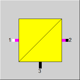
Line Connection |
|
|
|
1 |
Power Inlet |
|
|
2 |
Power Outlet |
|
|
3 |
Power Loss |
|
General User Input Values Physics Used References Displays Example
Component 156 (Power Converter) is used to model a power inverter that changes direct current (DC) to alternating current (AC), or a power rectifier that converts from AC to DC. In practice, the conversion may be performed either by means of electronic circuits or utilizing rotating mechanical equipment. In the simulation model, the heat losses of the electronics and the necessary shaft power to drive the rotating equipment are both expressed in terms of the conversion efficiency relative to the inlet power.
For simulation of photovoltaic inverters the performance model for grid-connected PV inverters developed by Sandia National Laboratories, USA (SAND2007-5036) can be used. For this performance model, an extensive collection of data sets has been implemented in the default values library of component 156.
| FMODE |
Flag to set the calculation mode Design / Off-design =0: Global |
| FEFF |
Method for specification of efficiency model
|
| FVOLT |
Method for specification of outlet voltage
|
| U2 | Outlet voltage |
| FFREQ |
Method to specify outlet frequency
|
| FREQ | Outlet frequency |
| NPHAS |
Flag to set the type of outlet current =0: Direct Current =1: One-phase alternating current =3: Three-phase alternating current
(Note: The specification of the current type at the inlet of the component is made via component 1 / component 33 on the electrical inlet line)
|
| EFF |
Efficiency |
| FEFFOD |
Method for part load calculation
|
| SMODEL |
Inverter Model Name |
| VAC |
AC voltage output |
| PACO |
Maximum AC power rating |
| PDCO |
DC power level at which the AC power rating is achieved |
| VDCO |
DC voltage level at which the AC power rating is achieved |
| PSO |
DC power required to start the inversion process (self-consumption) |
| C0 |
parameter defining the curvature (parabolic) of the relationship between AC power and DC power at the reference operating condition, default value of zero gives a linear relationship, (1/W) |
| C1 |
empirical coefficient allowing PDCO to vary linearly with DC voltage input, default value is zero, (1/V) |
| C2 |
empirical coefficient allowing PSO to vary linearly with DC voltage input, default value is zero, (1/V) |
| C3 |
empirical coefficient allowing C0 to vary linearly with DC voltage input, default value is zero, (1/V) |
| PNT |
AC power consumed by inverter at night (night tare) to maintain circuitry required to sense PV array voltage, (W) |
| VDCMAX |
Maximum DC voltage |
| IDCMAX |
Maximum DC current |
| MPPTLOW |
Maximum power point lower voltage limit |
| MPPTHIGH |
Maximum power point upper voltage limit |
|
Q1N |
Nominal inlet power |
|
EFFN |
Nominal efficiency |
| RLOAD | Calculated load |
| REFF | Calculated efficiency |
| QLOSS | Calculated losses |
| QAPP | Calculated apparent outlet power |
| QREAL | Calculated outlet power |
| QREACT | Calculated reactive outlet power |
| COSPHI2 | Outlet power factor |
In design mode of the simple efficiency model, the user has to specify
For the current input into the transformer, the following are defined
In design mode of the simple efficiency model, the user has to specify the conversion efficiency with the parameter EFF. The resulting outlet power Q2 will be calculated as Q2 = Q1*EFF, and if a logic line is connected to port 3, the respective losses will be written into the stream value Q (energy flow). Type of current, voltage and frequency of the electric line connected to the outlet port 2 of the power converter will be set as per the specifications of the user.
The SANDIA PV Inverter Performance Model (selected with Efficiency Model FEFF = 1) allows for describing the performance characteristic of a specific PV inverter type with a set of parameters. Since these data are derived from experiments with commercially available PV inverters, thus they already represent a fixed design. If a pre-configured data set for a specific inverter type is selected from the default value library, the respective value for PDCO (DC power level at which the AC power rating is achieved) will be used for the nominal inlet power Q1N, and design point efficiency EFFN will be derived from the ratio PACO/PDCO.
Depending on the setting of the method flag FEFFOD, the off-design calculation will use the design efficiency (FEFFOD = 0: Constant design efficiency EFFN), or the efficiency will depend on the ratio of inlet power to nominal inlet power as per the correction factor defined in the characteristic CEFF. The outlet power will then be calculated as Q2 = Q1*EFFN*CEFF(Q1/Q1N).
The Sandia performance model for grid-connected PV inverters (SAND2007-5036) describes the AC power output of the inverter (PAC) as a function of DC inlet power (PDC) with the following set equation:
PAC = [(PACO/(A - B)) - C * (A - B)] * (PDC - B) + C * (PDC - B)^2
The coefficients A, B and C are calculated with linear dependency of the DC inlet voltage (VDC) and type-specific parameters that describe DC power and voltage at rated AC power and the self-consumption at nominal DC voltage.
A = PDCO * [1 + C1 * (VDC - VDCO)]
B = PSO* [1 + C2 * (VDC - VDCO)]
C = C0* [1 + C3 * (VDC - VDCO)]
The individual parameters and coefficients are displayed with the same variable name as used in component 156, see the section User Input Values above. In addition, the data set for the PV inverter may include operating limits for maximum DC power and DC voltage, the range for DC voltage at the maximum power point which are checked in the calculation, if present. For information, the AC power consumed by the inverter at night to maintain circuitry required to sense PV array voltage is listed, but not actively used in the calculation.
Characteristic line 1 (CEFF): electrical efficiency
|
Characteristic line 1: electrical efficiency |
|
X-Axis 1 Q1/Q1N 1st point
. |
 |
Display Option 1 |
Click here >> Component 156 Demo << to load an example.