
|
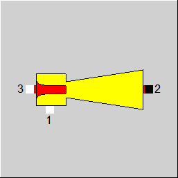
Line Connections |
|
|
|
1 |
Suction Port |
|
|
2 |
Discharge Port |
|
|
3 |
Motive Steam Inlet |
|
General User Input Values Physics Used Displays Example
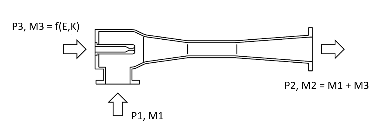
Component 154 (Steam Jet Vacuum Pump) represents a device used to create and maintain vacuum, and to remove gasses from the steam cycle, as for instance in the de-aeration of turbine condensers. Through acceleration in the nozzle, the steam vacuum pump uses the expansion work of the motive steam to generate a vacuum. In the suction chamber, the jet entrains the suction medium and accelerates its velocity. The pressure of the resulting mixture is raised when passing through the throat and the final diffuser section of the steam vacuum pump. Single stage steam jet vacuum pumps achieve a compression ratio P2/P1 of up to 10 given a sufficiently high expansion ratio of P3/P1. For higher compression ratios (or lower vacuum), multi-stage vacuum pumps are used which can be modelled by a series of steam jet vacuum pump units. If the suction medium is a gas, intercoolers may be used to condense the motive steam, which increases efficiency by reducing the amount of suction flow in the subsequent stages.
| FMODE |
Flag to set the calculation mode Design / Off-design
|
| FSPECX |
Method for specification of material equation handling (i.e. defining the two streams that are used for calculating the composition of the third)
|
| FMETHOD |
Flag to set the calculation method
|
| FTARGETOD |
Flag to set the target value of the off-design calculation;
|
|
ENAN |
Nominal effective nozzle area |
The mass flow of motive steam M3 that is needed for entraining the suction flow M1 depends on the type and the conditions (P1, T1) of the suction medium as well as on the required exit pressure P2 of the steam jet pump.

The motive steam flow is determined from the correlation described in the graph below (picture source: GEA Group) as the specific steam consumption b that describes the amount of motive steam per kg of equivalent water vapour suction flow (steam at 150°C).
.png)
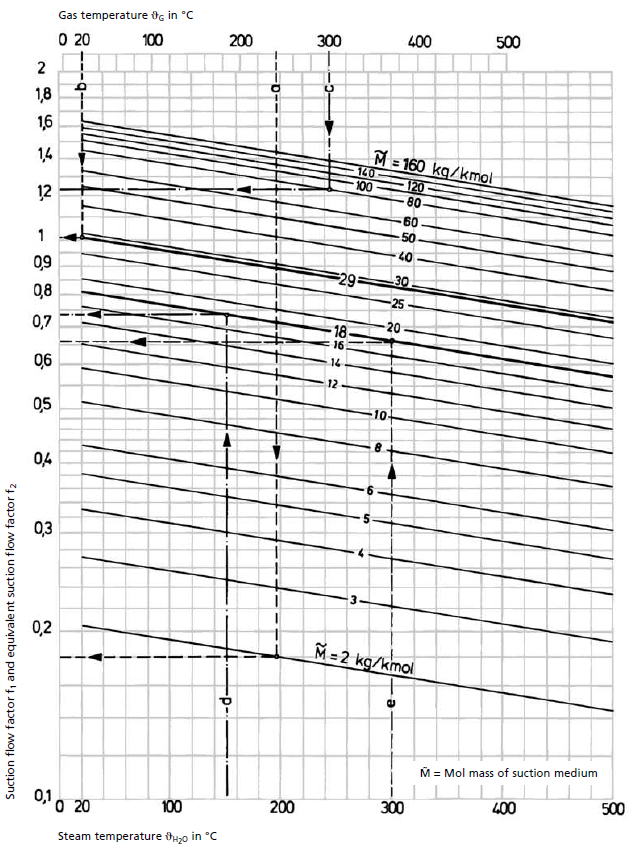
The parameters of this graph are the expansion ratio E=P3/P1 and the compression ratio K=P2/P1. The actual mass flow at the suction port is converted to the equivalent suction flow utilizing the graph below (picture source: GEA Group) which is valid for pure gases or gas mixtures (top x-axis) or steam flows (bottom x-axis) with the mean molecular mass of the suction fluid as parameter: M1_eq= f1/f2 * M1. The factor f1 equals 0.73537 for steam at 150°C used for the determination of the specific steam consumption b.

In design mode P1, M1, and P3 have to be specified, and the nozzle area of the steam jet is sized based on the speed of sound for the resulting flow of motive steam. Since the flow in the nozzle is always at the speed of sound, so that this value determines the flow through the nozzle as a function of the motive pressure P3 also under off-design conditions.
In off-design calculation mode, the nozzle area of the steam jet vacuum pump is fixed. For a given pump discharge pressure P2, the off-design calculation can either determine
In all three cases the solution will be determined through an iteration that uses the correlations of the two graphs above and the speed of sound for the motive steam which is a function of the effective nozzle area, P3 and M3.
Characteristic line 1 (CFP2P1): correction factor for motive steam flow = f (P2/P1)
|
Characteristic line 1: flow correction factor for motive steam flow |
|
X-Axis 1 P2/P1 1st point
. |
Characteristic line 2 (CFLNP3P1): correction factor for motive steam flow = f (ln(P3/P1)) - Attention: logarithmic scale!
|
Characteristic line 2: flow correction factor |
|
X-Axis 1 ln(P3/P1) 1st point
. |
|
MXCFM3M1: correction factor Flow CF = f ((P2/P1, ln(P3/P1)) |
| Correction factor for motive steam flow as a function of compression ratio (P2/P1) and the natural logarithm of the expansion ratio ln(P3/P1) - Attention: logarithmic scale! |
GEA Wiegand GmbH, Product Catalogue Jet Pumps, www.gea.com
HEI Standards for Steam Jet Vacuum Systems, 6th Edition, Heat Exchange Institute, Inc., 2007
DIN 28430, Messregeln für Dampfstrahlvakuumpumpen und Dampfstrahlkompressoren, Beuth Verlag, 2017
 |
Display Option 1 |
Click here >> Component 154 Demo << to load an example.