
EBSILON®Professional Online Documentation


|
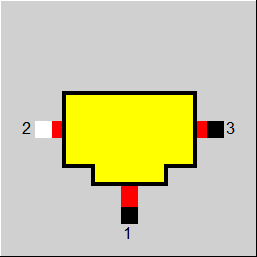
Line connections |
|
|
|
1 |
Outlet to the consumer |
|
|
2 |
Inlet from the connecting pipe |
|
|
3 |
Outlet to the connecting pipe |
|
General User Input Values Displays Example
Together with Components 148 and 150, this component forms a component group that allows to model a common steam header. The crucial difference compared to the other components of the type Mixer/Splitter (like e.g. Components 4, 18, 37, 60) is that only Pin 1 has a fixed flow direction (here: outlet). It is true that Pins 2 and 3 are defined as inlet and outlet respectively.
However, they can be both inlet and outlet. This makes the flow direction within the common steam header arbitrary. With negative mass flows M3 and M2 respectively, however, the inlet is implemented at Pin 3 and the outlet at Pin 2 due to the logic defined in EBSILON. In contrast, positive values for M2 and M3 imply the distribution that is “normal“ for EBSILON (Pin 2 represents the inlet, Pin 3 represents the outlet).
The particular feature of Component 149 (contrary to Components 148 and 150) is that one can set the mass flow M1 to be either defined from outside (FM=0) or to be undefined (FM=1). In the latter case the overall mass balance of the header is used to compute the mass flow M1 value. In the whole header modelled by header components 148-150 one needs exactly one Component 149 to be set to FM=1 in order to allow exactly one degree of freedom for the mass balance to be closed.
The component can be calculated with the following line types:
- Air
- Flue gas
- Steam
- Water (liquid)
- Crude gas
- Oil (with specifiable composition)
- Coal / solid matter
- Gas (fuel)
- User-defined
- 2-Phase liquid
- 2-Phase gaseous
- Saltwater
Depending on the flow distribution that results in the common steam header due to the mass balance, three situations are possible:
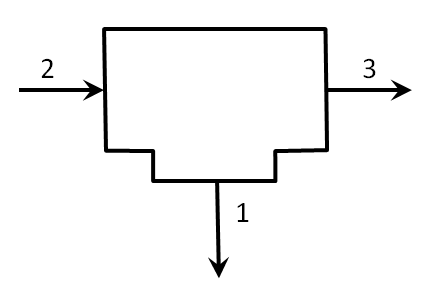
Situation 1: Distribution of Flow 2 into Flows 1 and 3 – all mass flows are positive
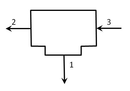
Situation 2: Distribution of Flow 3 into Flows 1 and 2 – M2 and M3 are negative
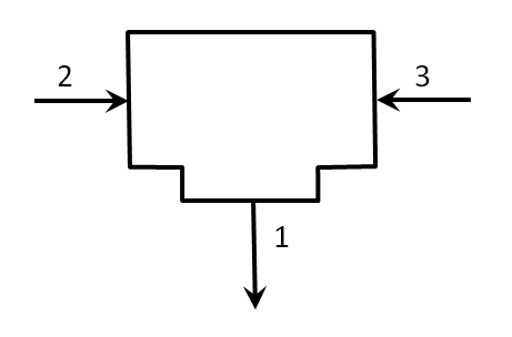
Situation 3: Mixing of Flows 2 and 3 to Flow 1 – M2 is positive, M3 is negative
|
FM
|
Mass flow definition (M1) =0: mass flow (M1) defined from outside the component 149 =1: mass flow (M1) not defined - in this case the mass flow M1 is defined from the overall mass balance within the header |
 |
Display option 1 |
Click here >> Component 149 Demo << to load an example.