

|
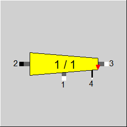
Line connections |
|
|
|
1 |
Representative feed |
|
|
2 |
Fluid outlet |
|
|
3 |
Inlet from previous instance |
|
|
4 |
Logic connection from distributing header |
|
General User Input Values Physics Used Diagrams Displays Example
The component 115 "collecting header" is used in conjunction with component 114 "distributing header" to model the collection of NBRANCH*NLOOPS equal mass flows into one collecting header. Only one of these identical mass flows is connected to component 115 at connecting point 1 ("Representative feed"). The collected mass flow leaves the component at connection point 2 ("Fluid outlet"). Via connecting point 3 ("Inlet from previous section") a second mass flow may enter the header. It is used if multiple headers are arranged in series and the outlet of one collector flows into the next one.
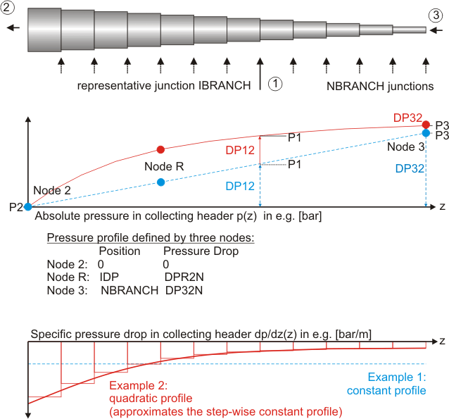
The user has to specify how many junction points NBRANCH are located along the header. It is assumed that the number of junction points is equal to the number of sections. This means that the last junction point in direction of flow is located upstream of the last header section. The first junction point is located directly at inlet 3 upstream of the first header section.
Since some of the collecting header parameters are normally identical to the ones of the distributing header both components can be synchronized. If synchronization is activated by FSYNC=1, 2, or 3 the parameters NBRANCH, NLOOPS, LSECT, and ISUN of the collecting header are read from the distributing header linked via the logic line. The three synchronization options differ in the way of pressure handling.
FSPECX allows defining on which pins a composition is to be specified. However, this flag can only be used if the material equations are integrated into the equation system.
(Model option -->Simulation --> Iteration, Level of integration of material equations).
|
FCONF |
Relative geometric arrangement to distributing header component 114
Like in Parent Profile (Sub Profile option only) Expression =0: Logical line not used, all values are specified independently in distributing and collecting header =1: Flow arrangement in the same direction =-1: Flow arrangement in opposite direction |
|
NBRANCH |
Number of sections and thus junction points in the header |
|
IBRANCH |
Position of representative junction point in the header (red triangle in the graphics). Used for FSYNC=0 to define the pressure path between feed and outlet.
|
|
NLOOPS |
Number of loops connected to each junction point |
|
IDP |
Position of node for pressure loss calculation (1<=IDP<=NBRANCH) |
|
FSPECM |
Definition of mass flow calculation method
Like in Parent Profile (Sub Profile option only) Expression =0: Inflow M3 given from external =1: Inflow M3 calculated from representative feed M2 and ratio M2M3 =2: Inflow M3 calculated from outflow M1 and ratio M2M3 |
|
M3M2 |
Ratio of M3 to M2 (used if FSPECM=1 or 2) |
|
FSPECP |
Handling of pressure drop
Like in Parent Profile (Sub Profile option only) Expression =1: Calculated pressure drops are impressed between all three connection points, pressure level is defined from one of the three lines =-1: Throttling at inlet P1 (only P2 and P3 are linked by internal pressure drop) =-2: Throttling at inlet P2 (only P1 and P3 are linked by internal pressure drop) =-3: Throttling at inlet P3 (only P1 and P2 are linked by internal pressure drop) |
|
FREPP |
Position of junction used for pressure calculation
Like in Parent Profile (Sub Profile option only) Expression =0: Use junction defined by IBRANCH =1: Use last junction to represent maximum pressure drop DP32 (IBRANCH=NBRANCH) |
|
LSECT |
Length of header section between two junction points |
|
FDADAPT |
Assumption for diameter profile along the header Like in Parent Profile (Sub Profile option only) Expression =0: constant diameter given by DDESIG =1: diameter profile to obtain constant velocity given by VDESIG |
|
DDESIG |
Header inner diameter (constant along header, used if FDPN=1/2 and FDADAPT=0) |
|
VDESIG |
Header design velocity (constant along the header, used if FDPN=1/2 and FDADAPT=1) |
|
FMODE |
Flag for calculation mode Expression =0: Global =1: local off-design (i.e. always off-design mode, even when a design calculation has been done globally) = -1: local design |
|
FSPECX |
Material-equation handling Expression =0: Any given |
|
FDPN |
Method for calculation of nominal pressure loss
Like in Parent Profile (Sub Profile option only) Expression =0: Given by parameter DP12N =1: Calculation single phase (faster computation than option 2) =2: Calculation single and two phase flow |
|
DPR2N |
Nominal pressure loss between inflow 1 and node IDP |
|
DP32N |
Nominal pressure loss between inflow 1 and outflow 3 |
|
FDPPL |
Method for calculation of part-load pressure loss
Like in Parent Profile (Sub Profile option only) Expression =0: Depending on mass flow =1: Depending on mass and volume flow =2: Constant at nominal value (calculated according to FDP12N) =4: Calculation single phase flow (faster computation than option 4) =5: Calculation single and two phase flow |
|
KS |
Equivalent sand roughness of inner pipe surface (used for model based pressure loss calculation) |
|
FQLOSS |
Method for calculation of heat losses to surrounding
Like in Parent Profile (Sub Profile option only) Expression =0: Specific heat loss prescribed by QSLOSS =1: Specific temperature drop prescribed by TSLOSS =2: Specific enthalpy drop prescribed by HSLOSS =3: Heat loss calculated by heat loss model |
|
QSLOSS |
Length-specific heat loss (constant along the whole header, used if FQLOSS=0) |
|
TSLOSS |
Length-specific temperature drop (constant along the whole header, used if FQLOSS=1) |
|
HSLOSS |
Length-specific enthalpy drop (constant along the whole header, used if FQLOSS=2) |
|
RATISOL |
Insulation material thickness (ratio of outer to inner diameter if insulation material, used if FQLOSS=3) |
|
LAMISOL |
Heat conductivity of insulation material (used if FQLOSS=3) |
|
CORQLOS |
Factor to tune the heat loss obtained from the heat loss model (used if FQLOSS=3) |
|
FSTAMB |
Definition of ambient temperature (required for model based heat losses)
Like in Parent Profile (Sub Profile option only) Expression =0: Given by parameter TAMB =1: Taken from superior SUN component with index ISUN
|
|
TAMB |
Ambient temperature (used if FQLOSS=3 and FSTAMB=0) |
|
ISUN |
Index of reference solar data component |
|
M1N |
Mass flow representative feed (nominal) |
|
M3N |
Mass flow inlet from previous instance (nominal) |
|
P2N |
Pressure inlet (nominal) |
|
H1N |
Enthalpy representative feed (nominal) |
|
H2N |
Enthalpy outlet (nominal) |
|
H3N |
Enthalpy inlet from previous instance (nominal) |
|
VR12N |
Specific volume at reference point 1-2 (nominal) |
|
VR32N |
Specific volume at reference point 3-2 (nominal) |
|
TAMBN |
Ambient temperature (nominal) |
The parameters marked in blue are reference quantities for the off-design mode. The actual off-design values refer to these quantities in the equations used.
|
QLOSS12 |
Heat loss between representative junction and fluid outlet |
|
QLOSS32 |
Heat loss of the complete header |
|
QLOSSA |
Mean length-specific heat loss |
|
DT12 |
Temperature drop between representative junction and fluid outlet |
|
DT32 |
Temperature drop over the complete header |
|
DP12 |
Pressure drop between representative junction and fluid outlet |
|
DP32 |
Pressure drop over the complete header |
|
DPSA |
Mean length-specific pressure drop |
|
DMAX |
Maximum diameter |
|
DMIN |
Minimum diameter |
|
RTAMB |
Ambient temperature used for calculation |
|
RNBRANCH |
Number of branches used for calculation |
|
RIBRANCH |
Representative branch used for calculation |
|
RNLOOPS |
Number of loops per branch used for calculation |
|
RLSECT |
Length of one section used for calculation |
|
RISUN |
Sun index used for calculation |
A number of NBRANCH*NLOOPS equal mass flows M1 enters the header component at NBRANCH junction points. In addition, a further mass flow M3 may enter the header. The mass flow M3 is either given from external or is defined by M1 or M2 and the ratio M3M2 between flow M3 from the previous component and fluid outflow M2.
M1 = (M2-M3) / (NBRANCH*NLOOPS).
The parameter NBRANCH describes the number of sections along the header. At the beginning (in direction of flow) of each section a mass flow M1*NLOOPS enters the header.
The incoming fluid streams M1 are added to the flow M3 at each junction point. In case no heat losses to the surrounding occur the specific enthalpy at the fluid outlet (2) is the mass flow weighted average of the specific enthalpies at inlets 1 and 3. This is the case if the specific losses of heat QSLOSS, temperature TSLOSS or enthalpy HSLOSS a set to 0.
Heat losses in the sections of the header can be considered by prescribing non-zero values for these parameters. The user has the choice between definition of a length-specific heat loss (FQLOSS=0), temperature drop (FQLOSS=1) or enthalpy drop (FQLOSS=2). The value defined by the user is used to calculate the specific enthalpy at the end of each section. This calculation is done for all sections in series. The inlet conditions of the downstream sections are given by the outlet conditions of the corresponding upstream section. Note that the specific heat loss, temperature drop or enthalpy drop is constant along the whole length. Due to the varying mass flow from section to section the temperature profile along the header is only linear if a constant temperature drop is chosen. Applying a constant specific heat loss will result in a non-linear temperature profile.
As a fourth option, a model based calculation of the heat losses is provided. The effective heat loss in each section is calculated from the difference between fluid and ambient temperature based on a radial heat conduction in the insulating material. The nominal heat loss in a section i of the header is calculated according to the formula
Q_0(i)=2*pi*LSECT*LAMISOL*1 / ln(RATISO) * CORQLOS * ( T_0(i) - Tamb_0) ,
where LAMISOL is the ratio of outer to inner insulation material diameter (constant along the header) and CORQLOS is a parameter to tune the model result. T_0(i) is the fluid temperature (at the middle of the collector) and Tamb_0 the ambient temperature.
In part-load operation it is assumed that heat losses are linear in the temperature difference between fluid and ambient air. Thus, losses are calculated based on the nominal values by means of
Q(i) = Q_0(i) * ( T(i) - Tamb) / ( T_0(i) - Tamb_0) .
Although the ambient temperature in the design point is only required if the model based calculation (FQLOSS=3) is selected the ambient temperature is stored as a reference point for the part-load heat losses.
Due to varying mass flow rates and diameter (optional) along the header the length-specific pressure drop along the header will not be constant. In order to avoid a detailed pressure drop calculation section by section it is assumed that the specific pressure drop can be approximated by a second-order polynomial. Integration of this polynomial along the header yields the pressure difference between two distinct locations, namely DP12 as the pressure drop between representative feed 1 and outflow 2 and DP32 as the pressure drop between inlet 3 and outlet 2. Three nodes are required to determine the coefficients of the polynomial. The first node is located at the inlet 3, the second at position IDP and the third one at outlet 2. The user can decide weather to
The pressure loss model described in component 113 is used here to calculate specific pressure losses (Pa/m) at the three nodes. This requires an assumption on the header diameter at these positions. Two options are available:
In the second option the diameter is calculated based on the nominal mass flow and density in the respective sections. Note that due to the calculation method a continuous profile of the diameter is assumed to approximate the section-wise constant profile in a real system.
The user has the following options for the calculation of the part-load pressure loss:
Synchronization with component 114 and selection of the pressure path (FREPP and FCONF)
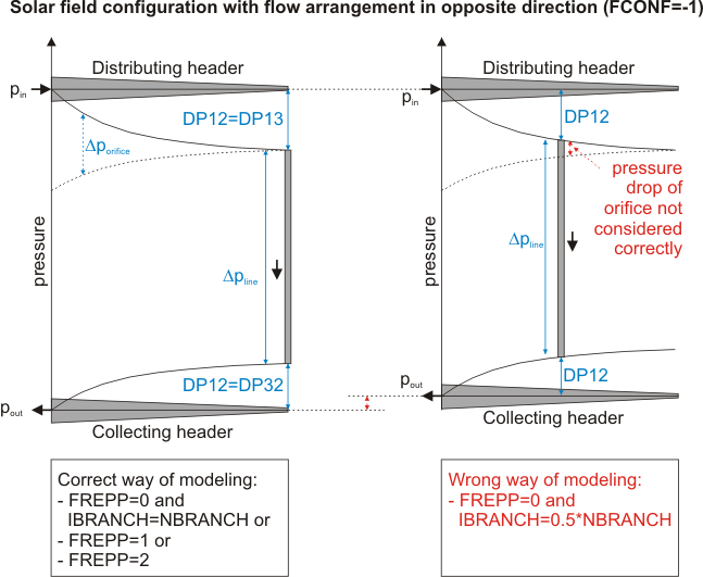
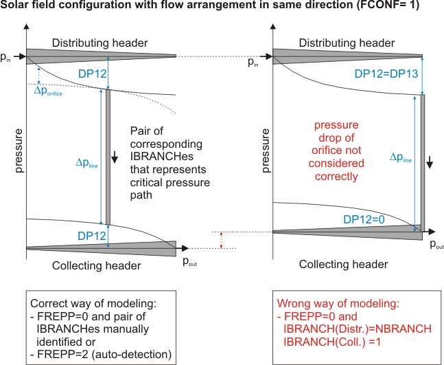
For solar applications equal distribution of mass flow on all parallel lines is favoured. Due to the pressure drops in distributing and collecting header the resulting pressure difference in all lines is not a priori the same. Assuming the same hydraulic resistance in the lines, the mass flow would not be equal. In the real application equal mass flows are forced by an additional resistance caused by passive orifices or manual valves. After trimming of the field all lines face the same mass flow.
After an ideal trimming of the field one line will have an additional resistance of zero. This line has to be considered when the pressure drop across the whole field is to be identified. For option FREPP=0 the user himself decides which branching/junction point is to be used for pressure calculation. The combination selected might not be the path of maximum pressure drop. While the user is completely free in the combination of IBRANCH values in distributing and collecting header when choosing FCONF=0, EBSILON®Professional automatically selects corresponding pairs based on the geometric arrangement of distributing and collecting header relative to each other for FCONF=1 or FCONF=-1 . The following relations are used between IBRANCH in distributing and collecting header
In case synchronization is active (FCONF=1 or -1) some other parameters are synchronized (read from distributing header), since they can be assumed equal in both components:
Please note that the user is responsible for identifying the path of maximum pressure drop when FREPP=0. This is especially true when selecting FCONF=1.
By flag FREPP=2 EBSILON®Professional helps to identify the path of maximum pressure drop. For this option the flag FSYNC=1 or -1 has to be selected and the distributing and collecting header have to be linked by a logic line. The program detects which pair of IBRANCH values in distributing and collecting header results in the highest overall pressure drop. These RIBRANCH values are used for the calculation instead of the values IBRANCH that might have been defined by the user.
 |
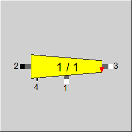
Display Option 1 |
 |
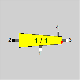
Display Option 2 |
 |
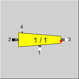
Display Option 3 |
 |
Display Option 4 |
Click here >> Component 115 Demo << to load an example.