
In the last chapter, you mapped a simple water/steam cycle. We now want to get it started. Select the entry "Calculation→Simulation" from the menu bar or click the "Simulate" button (F9). You will get an error message "Error in input data. Calculation failed." This is not surprising, because we have not specified any data set yet.
Nevertheless, a lot of data already are specified. When inserting a component, EBSILON®Professional automatically inserts a standard set of specification or default values for that component from the standard library. You can view these data in the property sheet (double-click on the component, or open the context menu with the right mouse button and select "Properties”).
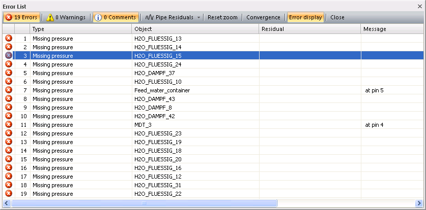
The error analysis informs us about the missing data. Click on "Calculation→Error Analysis". Notice that your drawing turns gray except for the line or the component containing the error. This is highlighted in colour. The details are displayed in the error window.

The column "Type" shows the types of errors that have occurred, and the field "Object" indicates the name of the component or line where the selected error occurred. Note that lines are also named just like the components.
The column "Message" gives a hint at which a error have occurred.
To define this value, take the "start value" from the component bar (last entry), select "Input value (boundary, start, schedule)" and place it on to the red line (note that you can edit your drawing even while you are in the error analysis).
After insertion, double-click on the start value inserted and type the desired value for the pressure P in the input field, e.g. 0.07 bar (if you prefer "psia", you can set this unit with the combo box for units).
Select the next error type, "missing mass flow". As you can see in the component list, it can be applied to quite a lot of lines. When you go through the list, the lines will be coloured one after the other. You can use the "lens"-icon to locate the coloured lines.
Place an "input value" on the water pipe between the pump and the steam generator and define the mass flow M, e.g. 200 kg/s. Instead of inserting a new "input value" you can copy the existing one with Ctrl+C/Ctrl+V. To remove the inlet pressure, highlight it and use the DEL key.
You should now close the error analysis window and do a simulation again.
The error analysis now tells you that there is only one missing mass flow, the merged inlet steam of the steam generator. The pressure and the enthalpy are missing on the same line. You can specify all three values in one "input value" component.
Instead of enthalpy, you can specify the temperature. For instance, specify P = 30 bar, T = 300 °C and M = 0 kg/s.
Note that there is an important difference between 0 and blank. If a field on the left is blank, it implies that the corresponding quantity is not defined. If you insert 0, a value of 0 is specified.
When you calculate again, you will notice that the pressure and the enthalpy of the cooling water are missing. Specify, for instance, P = 2 bar and T = 15 °C.
Now the calculation should done, although with warnings. The warnings results from the pump where the actual values lie outside the range of the specified characteristic. This can be ignored here.
If your drawing did not calculate successfully, you can compare it with "Example2.ebs". Open this file and use "Window→Tile" to display both windows. Compare the arrangement of components and lines and the specification values in the property sheet.
The resulting electric power is displayed when you leave the mouse pointer on the electric outlet of the generator. You can also set a value field (refer to chapter "Display of Results").